Manchester - England
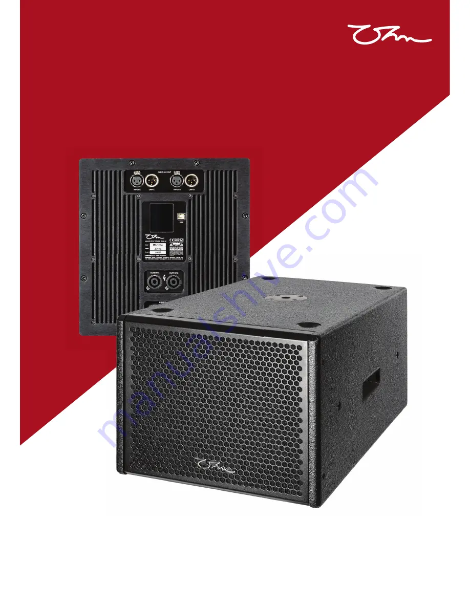
12” active 3 channel subwoofer
BRS-12A3
User Manual
Страница 1: ...Manchester England 12 active 3 channel subwoofer BRS 12A3 User Manual ...
Страница 2: ...A3 User Manual SCD ATT Version 1 2 29 04 2019 2 Wellington Close Parkgate Industrial Estate Knutsford Cheshire WA16 8XL United Kingdom Tel 44 0 1565 654641 Email info ohm co uk Website www ohm co uk aural ltd ...
Страница 3: ...ew Adjustment Screen Off LCD Touchscreen Menu Tree Initial System Testing Pro A Sync Download Software Start up Window Menu and Firmware Updates Controller Window Header Menu Main Tab Input Tabs PEQ Output Tabs PEQ Technical Specification Dimensions and Accessories 2D Drawing and Dimensions 3D Drawing Accessories and Spare Parts BRSC 12 Cradle Fitting Instructions Example System Set ups OHM Aural ...
Страница 4: ...eeping the packaging is a great way of making sure that any future vacations the unit needs to make are as secure as possible This BRS 12A3 has been made with our environment in mind There are many items used in its manufacture which are highly recyclable when the unit has reached the end of its useful life Please contact your local authority to arrange responsible disposal Unpacking Register your...
Страница 5: ... humidity or rain Liquid should not be stored placed on top of the unit Keep all ventilation surfaces clean and un obstructed This CLASS 1 product always requires an earth connection when connected to mains power Before powering up the system make sure all connections have been properly made Ensure all wiring is safe to use and complies to your local standards Unplug the unit when not in use durin...
Страница 6: ...ed system with parallel subwoofer output Rebated Baltic Birch Plywood construction Universal 100 to 240 Volt mains operation AC only Integrated Class D Power modules Passive cooling provides silent operation and low maintenance Fully integrated peak and RMS limiters with active Gain Reduction LCD touchscreen selection and adjustment to gain preset phase and channel mutes 2 kW Amplification 1 kW fo...
Страница 7: ... earth symbol connector on the trueCON plug Refit the cable clamp and tighten the collar onto the plug chassis Region Phase Live Non phase Neutral Earth Europe South Africa Brown Blue Green Yellow striped Australia New Zealand Brown or Red Blue or Black Green Yellow striped Brazil Yellow or Red Blue Green USA Canada Black White Green Yellow striped Asia Red Yellow Blue Black Green Yellow striped A...
Страница 8: ...following assignments Pin 1 Chassis Ground Pin 2 Phase positive hot signal Pin 3 Non phase negative cold signal When using the system with an unbalanced input link pins 1 3 together Do not overload the internal amplifiers by using unsuitable loads impedances The mid high outputs are designed to give maximum output at 4Ω Ensure all cabling is in good condition with suitable connectors terminated ap...
Страница 9: ...fier panel out of direct sunlight to reduce thermal loading and increase LCD visibility Only use genuine OHM accessories with this product In simple system set ups the unit can be controlled entirely via the touch screen display After initial power up the main screen on the LCD displays the Channel Meters screen This shows VU input and output gains gain reduction levels and peak RMS limit status T...
Страница 10: ...vidual taps are required to adjust items Pressing and holding screen buttons will not give consistent results When a menu page has been selected the page will time out after 15 seconds if no user input on the LCD is detected and return to the Channel Meters screen Preset selection and gain adjustment is remembered after power off and re applied when power is connected Adjustment All function butto...
Страница 11: ... on this page Mutes buttons are shown on left phase buttons on the right When the speaker icon is on a black backgrounds and has a diagonal line through it is muted The circle icon relates to phase When it is on a red background it is phased normally When it is on a black background it is 180 out of phase Channel Gain Minus buttonsreducethegain on each channel individually The plus buttons increas...
Страница 12: ...e the system has powered up completed its self test and is displaying the signal screen gently turn the input signal up and confirm all internal and external drivers are working as expected Basic individual channel adjustment to gain mute and phase can be done via the rear LCD screen or for more in depth features on any USB connected Windows or Mac computer running Ohm s Pro A Sync software Initia...
Страница 13: ...d is used to label the unit Click the Menu cog then click the Device Name box and type a suitable new name Press enter when complete 4 Type Displays the Model of the unit that is selected 5 Connection This will show the USB COM port which the unit is connected to 6 Current Preset Select by double clicking the box then on the triangle then the desired preset 7 Input Displays input type This unit us...
Страница 14: ...preset option This will re load the previously saved version of the file Overwrite this preset Once settings have been adjusted click the preset cog then click Overwrite this preset to save the new adjustments to the currently recalled preset This action cannot be undone Delete this user preset Selecting this option will delete the currently recalled preset This action cannot be undone Export curr...
Страница 15: ...ware is split into three screens MAIN IN and OUT There are 4 available input channel tabs 2 on BRS 12A3 and six available output channel tabs 3 on BRS 12A3 depending on which unit is connected To access any screen click the relevant tab The red tab denotes the screen currently being viewed Unavailable tabs are greyed out as shown by the In 3 4 Out 4 5 6 tabs on the picture shown on page 14 Main Ta...
Страница 16: ...e more gain reduction is applied the more compressed the audio signal will become Best audio performance is achieved when least gain reduction is applied The meter is marked in dB Maximum gain reduction is 12dB 4 RMS limit VU Meters This VU meter shows a visual indication of how much RMS limiting is being applied to the output RMS limiters allow outputs to be restrained without the typical compres...
Страница 17: ...licking the box and using the up down keys on the keyboard or the right of the box allow incremental changes Minimum frequency is 20 Hz Maximum is 24 kHz Gain Adjust the gain of the filter by clicking on the gain box and entering a number followed by the return key Minimum gain is 80dB maximum is 20dB Quality Use this box to change the quality width of the filter slope Click the box and enter a nu...
Страница 18: ...t to update the DSP RMS Release Time This setting adjusts the slope of gain reduction when the limiter is turning off Click the box twice then enter a numerical value Press enter and then click Submit to update the DSP 3 Output gain slider Directly control output gain by clicking and dragging the slider or rapidly clicking 3 times on the dB figure click delete and enter a number Press return to su...
Страница 19: ...e reflected in the graph 9 PEQ This table is split into 10 columns Clicking the number turns that filter on and off EQ type Click this box then the drop down triangle and a pop up box will appear with a choice of filter options are available Frequency Click the box once enter a number and press enter to change the frequency of that node Clicking the box and using the up down keys on the keyboard o...
Страница 20: ...R input with parallel link outputs Protection Internal multi band Peak and RMS Limiter DC HF and thermal protection PRODUCT FEATURES Components 1 x 12 Low Frequency Driver Crossover Variable Connectors 2 x XLR female 2 x XLR male 2 x 4 pole speakON and 1 x powerCON True1 Connector male 1 x powerCON True1 Connector female Dimensions H x W x D mm 333 3 x 400 x 606 Weight kg 25 6 Shipping Weight kg 2...
Страница 21: ...325 mm 400 mm 333 3 mm Dimensions and Accessories TP 1 adjustable threaded pole TP 1P threaded Mounting Plate BRSC 12 Cradle 1 x 12 low frequency driver BRS 12A3 steel grill assembly BRS 12A3 backplate assembly Steel OHM Logo Accessories and Spare Parts 3D Drawing 2D Drawing with Dimensions ...
Страница 22: ...ble for application type and weight of cabinet mounted and any supporting structure is stable enough to support the load The cradle can be used in a variety of positions for either ceiling floor or wall mounting and can be fitted to work from either top or bottom of the cabinet Ceiling mounted Either directly or using truss clamps Floor mounted NB if mounting from the bottom position remove feet W...
Страница 23: ...A3 BRS 12 2 solution BRS 12A3 User Manual SCD ATT Version 1 2 29 04 2019 23 BRT 6 x 4 BRT 26 x 2 BRW 26 x 2 BRT 8 x 2 BRW 28 x 1 BRT 10 x 1 BRT 6 x 4 BRT 26 x 2 BRW 26 x 2 BRT 8 x 2 BRW 28 x 1 BRT 10 x 1 Example System Set ups ...
Страница 24: ...y and will invalidate the remaining warranty period We reserve the right to use used components if new items are no longer available or subject to long delivery times which would excessively delay the return of products back to the user Wear and tear incorrect adjustment and cosmetic finishes including accidental damage are not covered under this warranty For electronic equipment loss of data setu...
Страница 25: ...your finger excessively dry wet Poor sound quality Check impedance loading on mid high outputs This unit is designed to work into 4Ω loads reducing this impedance beyond 4Ω will impact sound reproduction and reliability Buzz from amplifier when input leads connected Ensure there is a good earth connected to the unit Check signal input leads for conductor continuity Any input source needs to be con...
Страница 26: ...3 User Manual SCD ATT Version 1 2 29 04 2019 26 aural ltd Wellington Close Parkgate Industrial Estate Knutsford Cheshire WA16 8XL United Kingdom Tel 44 0 1565 654641 Email info ohm co uk Website www ohm co uk ...