CHAPTER 3 MAINTENANCE PROCEDURES
Valor
™ 2000/4000 Series Service Manual
3-3
Ohaus Corporation www.ohaus.com
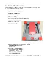
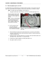
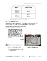
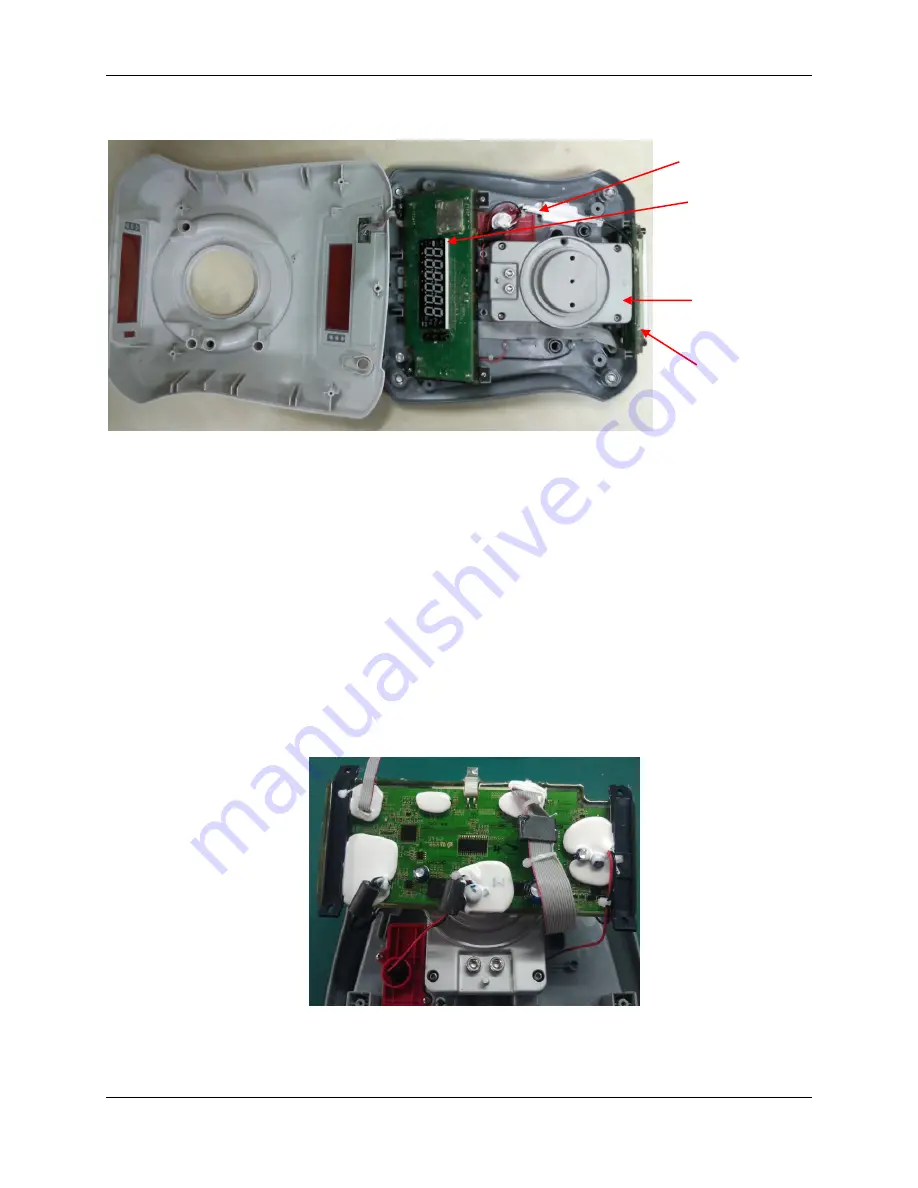
Figure 3-2. Top and Bottom Housings
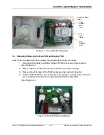
3.4 Removing/Replacing the Main PCB and Display PCB
If the PCBs are suspected of being faulty, they should be replaced, as follows:
1.
Disconnect the C
able connecting the Main PCB to the scale’s power system.
(See Figure 3-2.)
2. Remove the four screws that secure the PCB to the bottom housing.
3. Remove the white glue on the PCB that secures the load cell connector.
4. If either the Main PCB or the Load Cell is to be replaced, note the order of the wire
colors and then disconnect the Load Cell Cable from the Main PCB.
(See Figure 3-2.)
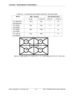
Figure 3-3. Main Printed Circuit Board.
Load
Cell
Frame
Load Cell Cable
leads.
Front
Display/
Main
PCB
Rear
Display
PCB
Содержание VALOR 4000
Страница 3: ......

