


CHAPTER 1
GETTING STARTED
1.6 HARDWARE SETUP OR DISASSEMBLY
Both the T51P and T51XW connect to a base scale through a Load Cell Cable that connects to
the Indicator’s Main Printed Circuit Board (PCB). Each model has a mounting bracket that can
be attached to a column mount bracket or a wall mount. To remove the mounting bracket,
remove the threaded knobs, holding the Indicator by hand.
CAUTION
:
ELECTRICAL SHOCK HAZARD. REMOVE ALL POWER CONNECTIONS TO THE
INDICATOR BEFORE SERVICING OR MAKING INTERNAL CONNECTIONS.
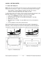
The process of opening the Housing varies slightly for each model:
T51P:
1. Remove the four Phillips head screws
from the rear housing.
2. Open the housing; disconnect the
ribbon cable from the top of the PCB.
T51XW:
1. Remove the four hex head screws from
the rear housing.
2. Open the housing by carefully pulling
the top of the front housing forward.
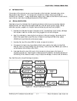
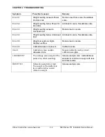
Below is a diagram of the T51’s Main PCB, with connectors, jumpers, terminals and switches
indicated.
Figure 1-3. Printed Circuit Board (PCB), T51 Indicator.
Power Supply
connector
Battery
connector J2
(T51P only)
Alternate
Load Cell
Terminal J4
Sense
Jumper W1
Sense
Jumper W2
Security Switch
SW2
RS232
Terminal J7
(T51XW only)
External Input
Terminal Block
COM2
Connector J8
(Optional:
RS232 or
RS422/485)
Load Cell
Connector Plug
Recharge
option-T51P
(opposite side)
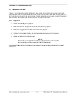
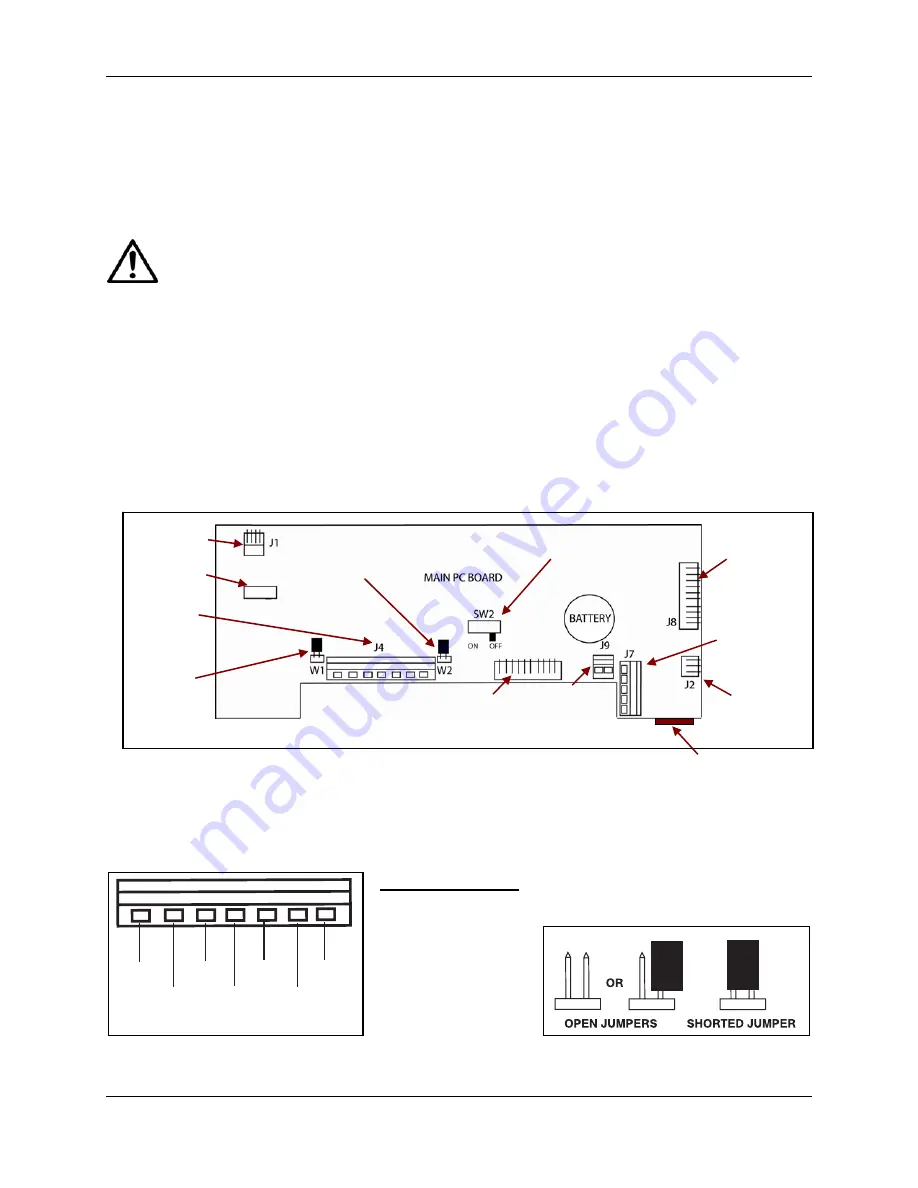
1.6.1 Jumper
Connections
RS232 Pin Connector
(T51P only)
For a 4-wire load cell with no sense wires, short Jumpers W1 and W2.
For a 6-wire load cell that includes sense wires, open Jumpers W1 and W2.
For load cells with an extra ground shield wire, connect the shield to the center position (GND).
+EXC +SIG -SIG -EXC
+SENS GND -SENS
Figure 1-4. Load Cell wiring.
Pin Connection
J4-1 +Excitation
J4-2 +Sense
J4-3 +Signal
J4-4 GND
J4-5 –Signal
J4-6 –Sense
J4-7 –Excitation
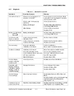
Figure 1-5. Open/shorted jumpers.
5000 Series T51 Indicator Service Manual
1-5
Ohaus Corporation www.ohaus.com
Содержание T51P
Страница 2: ......
Страница 4: ......
Страница 38: ...CHAPTER 5 PARTS LISTS DIAGRAMS Ohaus Corporation www ohaus com 5 6 5000 Series T51 Indicators Service Manual ...
Страница 41: ......
Страница 42: ... 80252587 P N 80252587 SERVICE MANUAL 5000 SERIES T51 INDICATORS ...


