


Officine Gullo
10
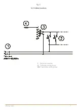
PIPE FOR GAS CONNECTION
The gas connection must be done with steel or copper pipes, or otherwise with flexible steel pipes in compliance
with the national norms, if any exist. Each appliance must be provided with a cut-off cock for rapid interruption of the
gas supply. Once the appliance has been installed, it is necessary to check for gas leaks for the pipe fittings; do not
use a flame for this purpose but a non-corrosive substance such as soapy water or foamy substances as contained
in leakfinder sprays. All our appliances undergo careful testing: the type of gas, the operating pressure and the
category are indicated on the data plate.
NB:
The year of the appliance manufacture is shown in item “N” on the data plate. The first two numbers (e.g. 08..)
represent the year of manufacture.
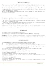
ELECTRIC CONNECTION
The appliance is supplied without the connection cable; to install it, proceed in the following way:
- Remove the back panel
- Push the connection cable through the cable channel, connect the conductor wires to the corresponding terminals
in the junction box and fix them into place.
- Block the cable with the cable blocker, and reassemble the panel. The earth wire must be longer than the others so
that if the cable blocker should break, it will disconnect after the tension wires.
N.B. The connection cable must have the following characteristics: it must be type H05RN-F and must have an
adequate section for the power of the appliance (see technical data table).
EQUIPOTENTIAL
The appliance must be connected to an equipotential system.
The connection screw is positioned at the back of the appliance and is identified by the symbol
.
Attention!
The manufacturer will neither be held responsible for, nor will give any compensation during the guarantee
period for any damage caused, and which is due to inadequate installations not compliant with the instructions.
CHECKING HEAT OUTPUT
The appliances must be checked in such a way as to verify that the heat output is correct:
•
The heat output (thermal power) is indicated on the data plate of the appliance;
•
Firstly, check that the appliance can be used with the type of gas supplied; then check that the indication
on the plate corresponds to the gas to be used. For converting to another type of gas, check that the type
of gas complies with what is stated in this instruction manual.
The pressure is read with a gauge (minimum resolution of 0.1 mbar) inserted in the relative pressure outlet.
Remove the hermetically closed screw and insert the gauge pipe.
After reading, put back the screw tightening it hermetically and check for pressure leaks.
Connection for liquid gas G30/G31
The connection pressure for liquid gas is 30 mbar with butane and 37 mbar with propane.
Check the plate, read the pressure and verify that the description of the nozzle installed corresponds to the one
supplied by the manufacturer.
Connection with natural gas H G20
The connection pressure for natural gas is 20 mbar.
Check the plate, read the pressure and verify that the description of the nozzle installed corresponds to the one
supplied by the manufacturer.
11
Officine Gullo
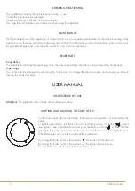
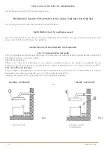
CHECKING PRIMARY AIR TO THE MAIN BURNERS AND PILOT NOZZLES
All the burners are fitted with an air regulator by means of which the primary air can be varied thanks to an adjustable
bush that can be locked with a screw. In the Burner Technical Data table you will find the approximate values for the
“h” parameter (primary air). The flow of primary air must be regulated so there is no detachment of the flame when the
burner is cold or a return of the flame when the burner is hot.
The pilot air is regulated when the appliance is tested and inspected for the gas it is set for.
If you are going to change to a different type of gas, regulate the air by means of the adjusting bush until the flame
stops sputtering and becomes an intense blue colour.
BURNERS TECHNICAL DATA TABLE
TPS4G
Burner max max 7 kW - min. 4 kW
12,68 kWh/kg
G30
BUTANE
30 mbar
12,87kWh/kg
G31
PROPANE
37 mbar
9,45 kWh/m
3
st.
G20
NATURAL GAS H
20 mbar
Burner Injector 1/100 mm
Min. output adjustment 1/100 mm
Pilot Injector 1/100 mm
Consumption
130A
100
20
kg/h 0,552
130A
100
20
kg/h 0,544
195
adjustable
35
m
3
st./h 0,740
TPS8G
Burner max 12 kW- min. 7 kW
Burner Injector 1/100 mm
Min. output adjustment 1/100 mm
Pilot Injector 1/100 mm
Consumption
165
130
19
0,937 kg/h
165
130
19
0,937 kg/h
260
130
27
1,27 m
3
st./h
RULES FOR CONVERTING AND INSTALLING OTHER TYPES OF GAS
Our appliances are tested and regulated for liquid gas.
The conversion or adaptation to another type of gas must be carried out by a specialized technician. The nozzles
for the various types of gas are in a packet supplied with the appliance and are marked in hundredths of mm (see
the technical data table).
SUBSTITUTING THE NOZZLE IN THE COUP DE FEU BURNER
Remove the panel and with a suitable spanner substitute the nozzle with another, suitable one.
Adjust the minimum flame by turning the by-pass screw either to the right or to the left until heat output reaches 4 kW.
The primary air of the all plate burner does not need adjusting.
Attention:
If liquid gas is used, the minimum flame adjustment screw must be screwed right down.