background image

15

Officine Gullo

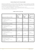
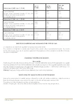
Burner max 3,5 kW- min. 1,15 kW 

G110

8 mbar

G150.1

8 mbar

Town gas

G110

10 mbar

Injector (marking)

By-pass (screw asjustment (number of turns anti-

clockwise from fully closed position)

Air adjustment (mm)

250

1/2

11,0

250

1/2

11,0

235

1/2

11,0 

Burner max 5,5 kW- min. 1,55 kW

Injector (marking)

By-pass (screw asjustment (number of turns anti-

clockwise from fully closed position)

Air adjustment (mm)

340

3/4

8,5

340

3/4

8,5

320

3/4

8,5

Burner max 7,5 kW- min. 2,5 kW

Injector (marking)

By-pass (screw asjustment (number of turns anti-

clockwise from fully closed position)

Air adjustment (mm)

450

1+1/2

10,0

450

1+1/2

10,0

390

3+1/2

10,0

RULES FOR CONVERTING AND INSTALLING OTHER TYPES OF GAS

Our appliances are tested and regulated for liquid gas (see plate inside).

The conversion or adaptation to another type of gas must be carried out by a specialized technician. The nozzles 

for the various types of gas are in a packet supplied with the appliance and are marked in hundredths of mm (see 

the technical data table).

CHANGING THE OPEN RING NOZZLES

Main nozzles 

Take the rungs off, remove the burners and trays, with a size 12 spanner substitute the nozzles with the appropriate ones, regulate 

the primary air (h) (see the “burner” technical data table) unscrewing the securing screw. Once regulated, tighten the screw, adjust 

the minimum flame by turning the screw to the right or left until the thermal power reaches 1,15 kW for the 3,5 kW burner, 1,55 

for the 5,5 kW burner and 2,5 kW for the 7 kW burner.

Warning: 

If liquid gas is being used the minimum adjustment screw must be locked right down.

SUBSTITUTING THE NOZZLE IN THE COUP DE FEU BURNER

Remove the panel and with a suitable spanner substitute the nozzle with another, suitable one. Adjust the minimum 

flame by turning the by-pass screw either to the right or to the left until heat output reaches 4 kW.

The primary air of the all plate burner does not need adjusting.

Attention: If liquid gas is used, the minimum flame adjustment screw must be screwed right down.

Содержание DFS4P

Страница 1: ...INSTRUCTIONS FOR INSTALLATION AND USE DFS4P D3FS12P D2FS8P D2FPS12P GAS HOB FOR RESIDENTIAL AND PROFESSIONAL USE...

Страница 2: ...le the appliance s maximum power consumption The use of adapters multiple power boards and extension cords is not recommended 8 When not in use switch off the general power supply to the appliance and...

Страница 3: ...RULES FOR CONVERTING AND INSTALLING OTHER TYPES OF GAS 15 CHANGING THE OPEN RING NOZZLES 15 SUBSTITUTING THE NOZZLE IN THE COUP DE FEU BURNER 15 CHECKING FUNCTIONING 16 MAINTENANCE 16 SPARE PARTS 16 U...

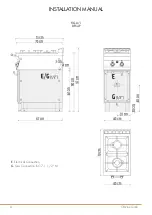
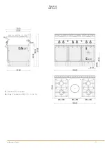
Страница 4: ...Officine Gullo 4 FIG A 1 DFS4P E Electrical Connection G Gas Connection ISO 7 1 1 2 M INSTALLATION MANUAL...

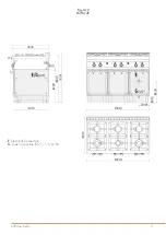
Страница 5: ...5 Officine Gullo Fig A 2 D3FS12P E Electrical Connection G Gas Connection ISO 7 1 3 4 M...

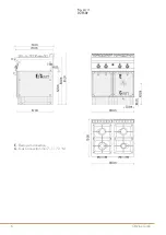
Страница 6: ...Officine Gullo 6 Fig A 3 D2FS8P E Electrical Connection G Gas Connection ISO 7 1 1 2 M...

Страница 7: ...7 Officine Gullo Fig A 4 D2FPS12P E Electrical Connection G Gas Connection ISO 7 1 3 4 M...

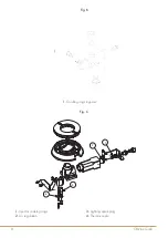
Страница 8: ...Bypass By pass four Oven by pass By pass horno FIG F PC GP CF GP FUOCHI FLAMME FEUX COOKING RINGS FUEGOS 562047300M00P00 1 2 3 4 1 Iniettore fuochi Einspritzventil flamme Injecteur feux Injector cook...

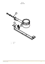
Страница 9: ...Gullo Fig D Coup de feu 6 FIG K TUTTAPIASTRA GL HPLATTENHERDEN PLAQUE SOLID TOP PLACA 1 Iniettore Einspritzventil Injecteur Injector Inyector 2 Gruppo pilota Z ndBrenner Veilleuse Pilot Piloto 1 Injec...

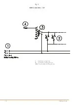
Страница 10: ...Officine Gullo 10 WIRING DIAGRAM TOP 1 Electrical connection 2 Push button starting burner 3 4 Power station starting burner Fig E...

Страница 11: ...y concerning room ventilation and discharging gas emissions N B The manufacturer declines any responsibility for direct or indirect damage caused by improper or incorrect installation alterations main...

Страница 12: ...tion of fire and panic Connection and installation of appliance ventilation and exhaust removal systems shall be done according to the Manufacturer s instructions and by qualified technicians and acco...

Страница 13: ...nce see technical data table EQUIPOTENTIAL The appliance must be connected to an equipotential system The connection screw is positioned at the back of the appliance and is identified by the symbol At...

Страница 14: ...nse blue colour BURNER TECHNICAL DATA TABLE Burner max 3 5 kW min 1 15 kW 12 8 kWh kg G30 BUTANE 30 mbar 12 8 kWh kg G31 PROPANE 37 mbar 9 45 kWh m3st G20 NATURAL GAS H 20 mbar Burner injector 1 100 m...

Страница 15: ...are in a packet supplied with the appliance and are marked in hundredths of mm see the technical data table CHANGING THE OPEN RING NOZZLES Main nozzles Take the rungs off remove the burners and trays...

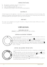
Страница 16: ...a symbol which indicates to which burner the knob corresponds To light turn the knob to the left from position 0 to the symbol see figure keep it pushed down and press the button with the symbol unti...

Страница 17: ...he desired effect is achieved The brass details should then be dried Do not use polish as this is suitable for maintaining the gloss but not the antique finish and could result in an effect that is no...

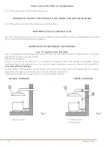
Страница 18: ...ble manually NATURAL DISCHARGE FORCED DISCHARGE 1 Extractor hood 1 Extractor hood 2 Interlocking Fig 1 Fig 2 WHAT TO DO IN THE EVENT OF A BREAKDOWN Turn off the gas tap and notify the after sales serv...

Страница 19: ...19 Officine Gullo...

Страница 20: ...Tel 39 055 656 0324 info officinegullo com Via Della Torricella 29 Antella Bagno a Ripoli 50012 Florence Italy OFFICINEGULLO COM en international V 2 3 12 18...

Отзывы: