Officine Gullo
12
INSTALLATION
•
The operations for installing, conversions for use with other types of gas and starting up must be done only
by qualified personnel whose qualifications comply with the norms in force.
•
Gas installations, the electrical connections and the rooms in which the appliances are installed must comply
with the norms in force in the Country in which the installation is carried out; above all, the appliance must
be installed in a well ventilated room, preferably under an extractor hood, so as to ensure the complete
extraction of gas emissions which are formed during combustion. The air necessary for combustion is 2m
3
/h
per kW of power installed.
Attention:
In accordance with international rules, when connecting the appliance, an automatic device enabling the
disconnection of all contacts from the mains, must be installed above it; this device must have a contacts opening
of at least 3 mm.
CHECKING FOR ADEQUATE VENTILATION
Make sure that the air intake into the room where the appliance is installed is sufficient for an adequate change of air, as
specified by regulations in effect.
The appliances installed in buildings open to the public must satisfy the following requirements.
Installation rules
The installation and maintenance of the appliance must be done according to the correct procedures and regulation
texts in use, particularly:
• safety standards for the prevention of fire and panic.
Connection and installation of appliance, ventilation and exhaust removal systems, shall be done according to the
Manufacturer’s instructions and by qualified technicians and according to the regulations in effect. The electric wiring shall
conform to the regulations in effect.
All fire prevention codes shall be observed.
a) General indications
(Rules valid for GB only)
- For all appliances:
Gas safety Regulations, 1984; Health and safety at Work Act, 1974 Codes of Practice, BS 8173, 1982, The Building
Regulations 1985; The Building Standards Regulations, 1981, the IEE Regulations and the by-laws of the local Water
Undertaking.
The local gas Region or LPG supplier and the local authority and the relevant recommendation of the British Standards
(latest editions) concerned.
The installation, transformation and repair of appliances for professional kitchens as well as removal due to malfunction,
and the supply of gas, may be made only by means of a maintenance contract stipulated with an authorized sales office
and in observance of technical regulations.
The appliance can be installed by itself or in a series side by side with appliances produced by us.
There must be a minimum distance of at least 10 cm between the appliance and the sides of the nearby cabinets made
of inflammable material.
Take suitable measures to guarantee thermal insulation of the inflammable sides, such as, for example, the installation of
protection against radiation.
The appliances must be installed in a suitable manner, observing the safety standards.
The small feet are adjustable to level the appliance.
13
Officine Gullo
PIPE FOR GAS CONNECTION
The gas connection must be done with steel or copper pipes, or otherwise with flexible steel pipes in compliance
with the national norms, if any exist. Each appliance must be provided with a cut-off cock for rapid interruption of the
gas supply. Once the appliance has been installed, it is necessary to check for gas leaks for the pipe fittings; do not
use a flame for this purpose but a non-corrosive substance such as soapy water or foamy substances as contained
in leakfinder sprays. All our appliances undergo careful testing: the type of gas, the operating pressure and the
category are indicated on the data plate.
NB:
The year of the appliance manufacture is shown in item “N” on the data plate. The first two numbers (e.g. 08..)
represent the year of manufacture.
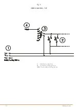
ELECTRIC CONNECTION
The appliance is supplied without the connection cable; to install it, proceed in the following way:
- Remove the back panel
- Push the connection cable through the cable channel, connect the conductor wires to the corresponding terminals
in the junction box and fix them into place.
- Block the cable with the cable blocker, and reassemble the panel. The earth wire must be longer than the others so
that if the cable blocker should break, it will disconnect after the tension wires.
N.B. The connection cable must have the following characteristics: it must be type H05RN-F and must have an
adequate section for the power of the appliance (see technical data table).
EQUIPOTENTIAL
The appliance must be connected to an equipotential system.
The connection screw is positioned at the back of the appliance and is identified by the symbol
.
Attention!
The manufacturer will neither be held responsible for, nor will give any compensation during the guarantee
period for any damage caused, and which is due to inadequate installations not compliant with the instructions.
CHECKING HEAT OUTPUT
The appliances must be checked in such a way as to verify that the heat output is correct:
•
The heat output (thermal power) is indicated on the data plate of the appliance;
•
Firstly, check that the appliance can be used with the type of gas supplied; then check that the indication
on the plate corresponds to the gas to be used. For converting to another type of gas, check that the type
of gas complies with what is stated in this instruction manual.
The pressure is read with a gauge (minimum resolution of 0.1 mbar) inserted in the relative pressure outlet.
Remove the hermetically closed screw and insert the gauge pipe.
After reading, put back the screw tightening it hermetically and check for pressure leaks.
Connection for liquid gas G30/G31
The connection pressure for liquid gas is 30 mbar with butane and 37 mbar with propane.
Check the plate, read the pressure and verify that the description of the nozzle installed corresponds to the one
supplied by the manufacturer.
Connection with natural gas H G20
The connection pressure for natural gas is 20 mbar.
Check the plate, read the pressure and verify that the description of the nozzle installed corresponds to the one
supplied by the manufacturer.
Содержание DFS4P
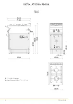
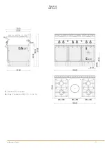
Страница 5: ...5 Officine Gullo Fig A 2 D3FS12P E Electrical Connection G Gas Connection ISO 7 1 3 4 M...
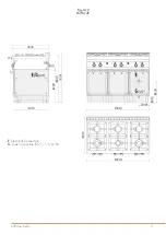
Страница 6: ...Officine Gullo 6 Fig A 3 D2FS8P E Electrical Connection G Gas Connection ISO 7 1 1 2 M...
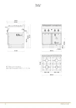
Страница 7: ...7 Officine Gullo Fig A 4 D2FPS12P E Electrical Connection G Gas Connection ISO 7 1 3 4 M...
Страница 19: ...19 Officine Gullo...


