background image


6

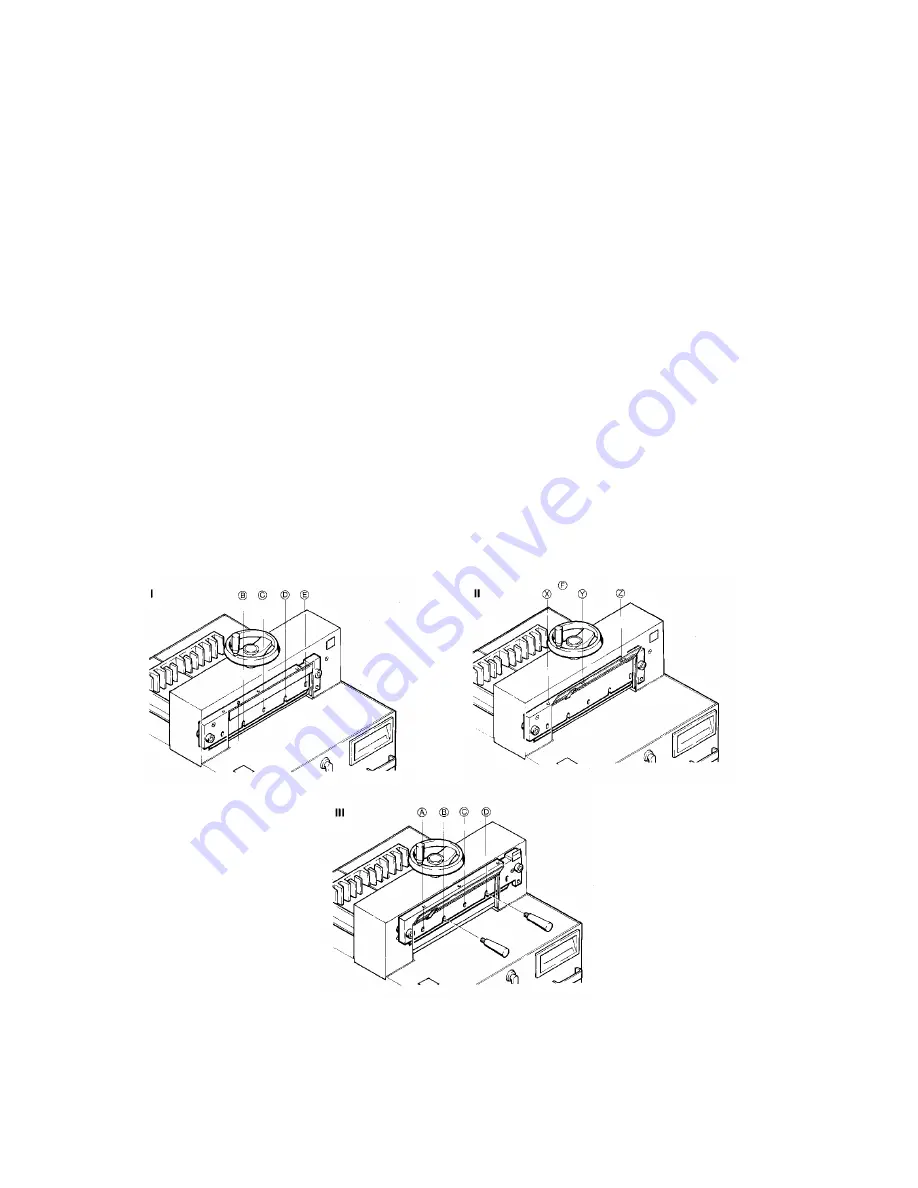
10.  Screw in knife screws (A and C) – snuggly, don’t tighten. 
11.  Remove knife holders.  Screw in knife screws (B and D) – snuggly, don’t tighten. 
12.  Spread one to three sheets of paper across the entire cutting length.  Bring the knife (#17) 

down.  Release only one push button (#5) and turn main switch (#11) to position “0” (off) 
again to stop the knife in its lowest position. 

13.  Screw in knife screw (E) – snuggly, don’t tighten. 
14.  The parallel adjustment of the knife is done via the knife adjustment screws. 


Push knife down by screwing in the knife adjustment screws (X, Y, and Z) evenly, until the 
paper is cut across its whole length. 
 

15.  Should the scope of the adjustment available by means of the knife adjustment screws be 

insufficient, resort to the knife depth adjustment screw (#4).  Turn it in steps of half a turn 
clockwise (+).  After each step a test cut has to be executed.  If the paper is cut through only 
on one side, proceed with parallel adjustment of knife as described under (#12 and #14). 
 
IMPORTANT – Both the above methods (#14 and #15) of knife adjustment offer an 
adjustment range of approximately 5 mm (1 / 4”). 
 

16.  Tighten knife screws (B, C, D and E) firmly while the knife is lowered on the cutting stick. 
17.  Turn main switch (#11) to position “|” (on).  The knife returns to its home position. 
18.  Tighten knife screw (A) firmly.  Screw in securing screw for knife adjustment flap (#20). 
19.  Make a test cut with a paper pile using the full cutting height.  If necessary do a fin al 

adjustment with the cutting depth adjustment screw (#4). 

20.  IMPORTANT – The clamp bar must be adjusted in a way that the cutting edge of the knife in 

its home position is covered by the clamp bar. 


Содержание IDEAL 4810 (18-3/4'')

Страница 1: ...1 1 800 543 5454 801 927 3026 IDEAL CUTTERS Model 4810 18 3 4 Model 4810 11 18 3 4 Model 5210 20 1 2 Office Zone 1 800 543 5454...

Страница 2: ...asures in the cutting machine Records should be kept of these safety inspections Transportation of knives is only allowing specially designed wooden cases supplied by your local distributor When inser...

Страница 3: ...tablish the ready to cut status of the machine The yellow pilot light in the viewing window 14 comes on and indicates that the machine s is ready for use The model IDEAL 4810 11 does not have a re set...

Страница 4: ...ressure toward the machine The connection is released by pulling the crank towards the operator If the crank is disengaged the back gauge setting cannot be changed inadvertently Turn to the right back...

Страница 5: ...L 4810 11 Please note that with models IDEAL 4810 and IDEAL 5210 the re set button 12 must be pushed prior to activating the knife with the two push buttons 5 1 Turn the cutting depth adjustment screw...

Страница 6: ...nt resort to the knife depth adjustment screw 4 Turn it in steps of half a turn clockwise After each step a test cut has to be executed If the paper is cut through only on one side proceed with parall...

Страница 7: ...left between the knife guide plates Lubrication IMPORTANT Before removing any machine covers for service or maintenance always disconnect machine from power supply From time to time all moving parts...

Страница 8: ...rmal overload switch has popped out it can be re set after a short cooling period Should the thermal overload switch pop out again and cannot be re set even after a few minutes please contact your ser...

Отзывы: