167
TECHNICAL INFORMATION
TE
CHN
IC
AL I
NF
ORMA
TI
ON
Limit temperature
2 mm / 2.5 mm
2
1.6 mm / 1.5 mm
2
1.3 mm / 1.1 mm
2
0.9 mm / 0.5 mm
2
0.7 mm / 0.38 mm
2
0.5 mm / 0.15 mm
2
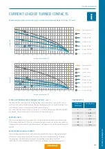
CURRENT LOAD OF TURNED CONTACTS
Nominal single contact current load for pin / slotted socket (nominal diameter 0.5 mm – 2.0 mm)
Number of
loaded wires
Derating factor
5
0.75
7
0.65
10
0.55
14
0.5
19
0.45
24
0.4
DERATING FACTOR
Current (A)
Ambient temperature (°C)
Current (A)
Ambient temperature (°C)
0
5
10
15
20
25
30
35
40
45
0
10
20
30
40
50
60
70
80
90
100
110
120
130
0
10
20
30
40
50
60
70
80
90
100
110
120
130
0
5
10
15
20
25
30
35
40
45
50
55
60
6
6
5
4
3
2
1
7
6
5
4
3
2
1
5
4
3
2
1
7
6
5
4
3
2
1
Limit temperature
3 mm / 4 mm
2
2 mm / 1.5 mm
2
1.6 mm / 1 mm
2
1.3 mm / 0.5 mm
2
0.9 mm / 0.38 mm
2
0.5 mm / 0.08 mm
2
0.7 mm / 0.15 mm
2
Current (A)
Ambient temperature (°C)
Current (A)
Ambient temperature (°C)
0
5
10
15
20
25
30
35
40
45
0
10
20
30
40
50
60
70
80
90
100
110
120
130
0
10
20
30
40
50
60
70
80
90
100
110
120
130
0
5
10
15
20
25
30
35
40
45
50
55
60
6
6
5
4
3
2
1
7
6
5
4
3
2
1
5
4
3
2
1
7
6
5
4
3
2
1
UPPER LIMIT TEMPERATURE OF STANDARD CONTACTS: +120 °C
The wire cross-section shown in the legend was connected as test cable. In the case of
multi-position connectors and cables, the heating is greater than it is with individual con-
tacts. For that reason, it is calculated with a reduction factor.
For connectors, the reduction factors for multi-core cables pursuant to VDE 0298-4:2013
are applied. The reduction factor is factored in at 5 live wires and up.
DERATING CURVE
The corrected current-carrying capacity curve, derived from the base curve determined
(0.8 x measured current). It factors in manufacturing tolerances as well as uncertainties
in temperature measurement and measurement arrangement. See derating measurement
method.
RATED CURRENT (NOMINAL CURRENT)
The metrologically determined current which is permitted t
o fl
ow continuously through
all contacts at the same time and will increase the contact temperature by 45 Kelvin.
The amperage is determined according to the derating measurement method
(IEC 60512-5-2:2002 (DIN EN 60512-5-2:2003) and derived from the derating curve.
Содержание MINI-SNAP K Series
Страница 10: ...ODU MINI SNAP Table of Contents...
Страница 16: ...ODU MINI SNAP Table of Contents...
Страница 17: ...CONFIGURATION GUIDELINE Correct configuring step by step CONFIGURATION Table of Contents...
Страница 22: ...ODU MINI SNAP Table of Contents...
Страница 37: ...89 SERIES K SERIES K FOR YOUR NOTES Table of Contents...
Страница 55: ...107 SERIES K SERIES K FOR YOUR NOTES Table of Contents...
Страница 61: ...113 SERIES K SERIES K FOR YOUR NOTES Table of Contents...
Страница 62: ...ODU MINI SNAP Table of Contents...
Страница 68: ...ODU MINI SNAP Table of Contents...


