104
1
2
3
4
5
6
7
8
9
10
11
12
13
14
15
16
17
18
19
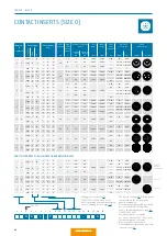
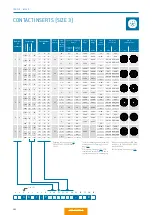
4 K
C – P
–
0
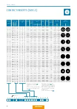
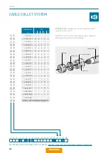
Clearance and creepage
distance
Test
voltage
2
kVe
ff
Nominal
voltage
5
kVrms
Termi-
nation
diameter
mm
Termination
cross-section
View on
termination area
Contact to
contact
mm
Contact to
housing
mm
AWG
mm
2
Pin piece
Socket piece
1.5
1
1.350
0.450
2.40
12
2.50
2.1
1.6
1.650
0.550
1.85
14
1.5
0.7
–
–
0.8
1
1.575
0.520
0.85
22
0.38
0.5
–
–
0.6
0.8
0.900
0.300
0.85
22
0.38
0.8
1
1.000
0.333
0.6
26
0.15
0.5
–
–
Number
of
contacts
0
7
5
3
0
4
0
Contact type
Te
rm
in
at
ion
Soc
ket
Pin
Solder
L
M
PCB
3
R
Solder
L
M
PCB
3
R
Solder
L
M
PCB
3
R
Part number
key
T
S
9
T
Q
9
T
0
9
J
G
O
J
O
O
F
G
0
F
D
0
F
O
0
1
Derating factor, see page 167.
2
SAE AS 13441:2004 method
3001.1.
3
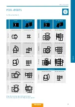
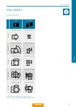
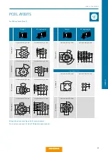
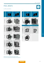
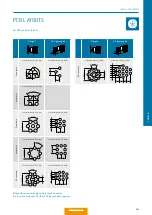
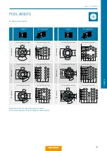
PCB layouts, see page 105.
4
Max. operating voltage at NN (sea
level) acc. to SAE AS 13441:2004
method 3001.1.
Further information on page 168.
5
Not compatible to competition.
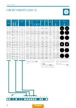
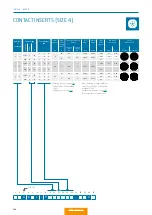
CONTACT INSERTS (SIZE 4)
Size (4)
Q
Q
Q
Contact
diameter
mm
Single
contact
nominal
current
1
A
2
24
18
0.9
7.5
0.7
7.5
6
SERIES K – INSERTS
Содержание MINI-SNAP K Series
Страница 10: ...ODU MINI SNAP Table of Contents...
Страница 16: ...ODU MINI SNAP Table of Contents...
Страница 17: ...CONFIGURATION GUIDELINE Correct configuring step by step CONFIGURATION Table of Contents...
Страница 22: ...ODU MINI SNAP Table of Contents...
Страница 37: ...89 SERIES K SERIES K FOR YOUR NOTES Table of Contents...
Страница 55: ...107 SERIES K SERIES K FOR YOUR NOTES Table of Contents...
Страница 61: ...113 SERIES K SERIES K FOR YOUR NOTES Table of Contents...
Страница 62: ...ODU MINI SNAP Table of Contents...
Страница 68: ...ODU MINI SNAP Table of Contents...

