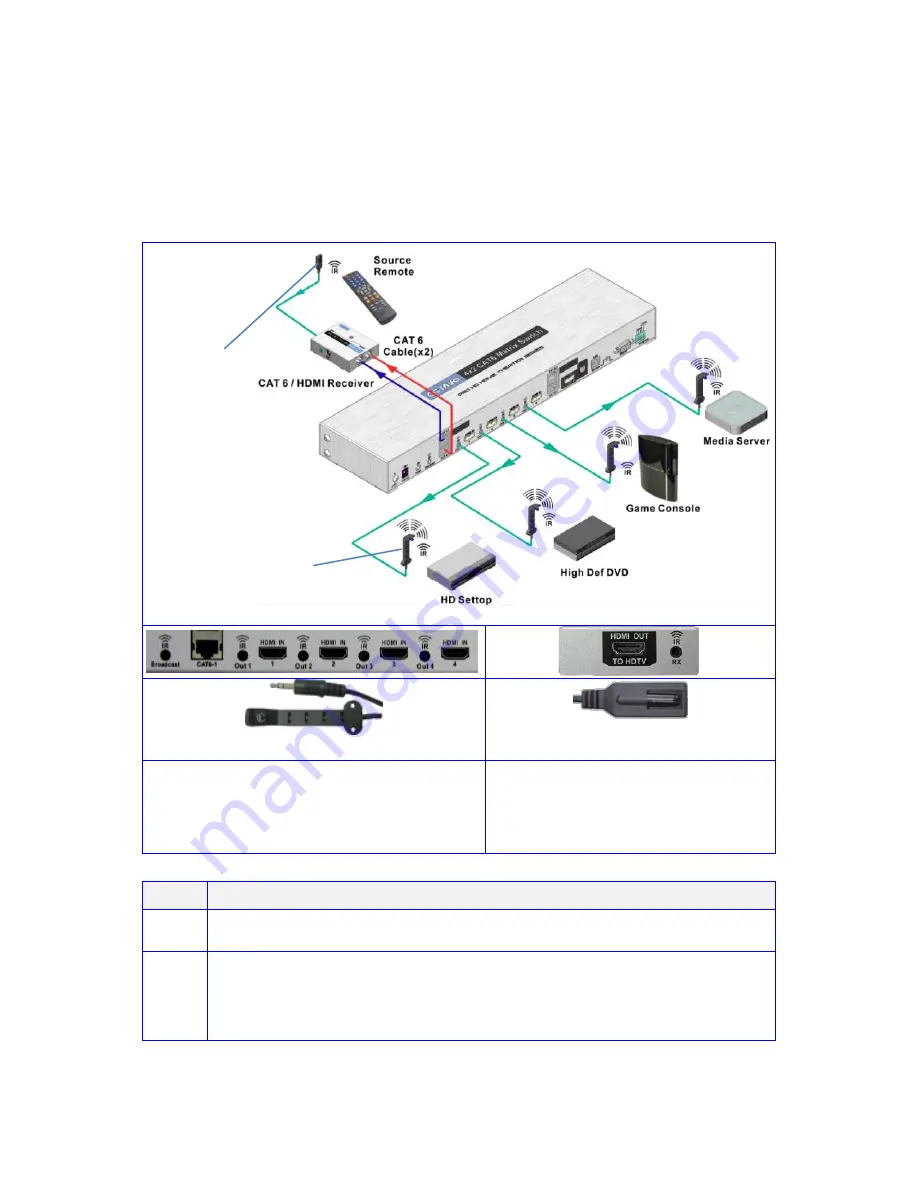
Octava HD42CATMX Скачать руководство пользователя страница 5


Infrared Overview:


-

IR can be independently Routed from any of the 2 connected Zones 

back to the Matrix plus connected Source devices.


-

All IR signals received from the zone receivers can be sent out thru 

the 

IR Broadcast port

 by connecting an IR Transmitter cable.


connect to IR Output (1-4) on 
Octava Matrix. Connect a IR 
transmitter cable to the IR Broadcast 
port if you need this feature.


connect to IR Input on Octava 
Zone Receiver (Rx) unit.


Step 

IR Installation 

Connect an Octava supplied IR Receiver cable to each Zone Rx unit. 
 

Connect an Octava supplied IR Blaster cable from the IR Output Port 
(1-4) on the Octava Matrix and position the Blaster Head over the IR 
Receiver window on the connected Source device.   

Connect IR 

transmitter cable to the IR Broadcast port if feature needed.


14- IR Transmitter 
/Blaster cable 

15- IR Receiver cable 

14-IR BlasterTransmitter cable 

15-IR Receiver cable 

Содержание HD42CATMX

Страница 1: ...1 Installation Guide Model HD42CATMX PRO HD HOME THEATER SERIES ...

Страница 2: ...ring non PoC Zone Receiver 8 Ethernet cable recommendations 9 Ethernet cable installation recommendations 9 Installation 10 Front Panel Control 13 Remote Control Guide 13 EDID Switch 14 USB Service Port 14 EDID Configuration 15 Changing EDID mode 16 RS232 Controls Commands 18 1 RU Rackmount 20 Disabling Enabling IR Remote Receiver 20 Warranty 21 Disclaimers 21 Specifications 22 ...

Страница 3: ...RJ 45 active simultaneously Routed IR from remote Zones to control Matrix plus Source devices Broadcast IR from remote Zones to control AV Receiver PoC Power over Cable to directly power in room Zone receivers via RJ 45 from matrix EDID Management plus custom EDID via USB service port Rack mountable 1 RU mounting lugs supplied Discrete IR codes for simple system integration Wired IR port for In ca...

Страница 4: ...tional 7 IR Output 1 4 connect Octava supplied IR Transmitter Blaster cable 8 HDMI Input 1 4 connect High Speed HDMI cables to Source device 9 HDMI Output connect High Speed HDMI cables to AVR or Display device 10 Dual RJ 45 Output A B CAT 6 connect Twisted Pair cables x2 to Octava Zone Receiver Rx unit 11 USB Port for custom EDID code updates 12 RS232 Port for external control of Matrix via PC or...

Страница 5: ...IR Broadcast port if you need this feature connect to IR Input on Octava Zone Receiver Rx unit Step IR Installation 1 Connect an Octava supplied IR Receiver cable to each Zone Rx unit 2 Connect an Octava supplied IR Blaster cable from the IR Output Port 1 4 on the Octava Matrix and position the Blaster Head over the IR Receiver window on the connected Source device Connect IR transmitter cable to ...

Страница 6: ...Rx unit you are working with PoC non PoC Refer to section Identifying Zone Receiver RX PoC Power over Cable Rx units are powered from the Matrix non PoC Rx units require a local 5V power supply Item Description 16 Power Indicator indicates Rx is receiving power 17 RJ 45 Input 1 2 connect to CAT6 Out 1 2 on Zones A D of Octava Matrix 18 HDMI Out to HDTV connect to HDTV using High Speed HDMI cable 1...

Страница 7: ...Receiver The Octava Matrix should include CAT 6 receivers with PoC power over cable Please verify by inspecting the first 6 serial number and confirm it is RXH3IR PoC Zone Receivers Serial Number PoC RXH3IRXXXXXX NON PoC Zone Receiver RX If you are upgrading or replacing only the matrix the Zone Receiver you installed may be older The Zone Receivers in the following table do NOT have PoC capabilit...

Страница 8: ...o the PoC socket on the Matrix Matrix PoC Power Port PoC Zone Receiver connect Octava supplied PoC power supply 5V 2 5A local power supply not required Powering non PoC Zone Receiver non PoC Zone Rx is powered by a local 5V PSU connected to the Power Socket on the Rx unit Matrix PoC Power Port non PoC Zone Receiver local power supply not required connect Octava supplied 5V PSU to Rx unit power soc...

Страница 9: ...ndard when terminating your CAT5 CAT6 or CAT7 cables Ethernet cable installation recommendations Use your cable suppliers recommended RJ 45 connector crimp tool with your CAT5 CAT6 or CAT7 cables and ensure you pay particular attention to the quality of the termination on all cables DO Recommend Use shielded CAT 6 or CAT 7 with good RJ 45 terminators Use a direct cable connection between the Matri...

Страница 10: ...nnect HDMI sources to HDMI IN 1 4 Connecting Output with HDMI cable 3 If you are connecting with HDMI cable Connect HDMI cable to HDMI output A and HDTV Connecting Output with Ethernet cables 4 Verify that the Zone Receiver you have supports PoC See page 7 If the Zone Receiver has PoC proceed to step 5 IF your Zone Receiver are non PoC proceed to Alternative steps A1 A5 Skip to page 12 5 Connect t...

Страница 11: ... your connections Note the 5V power of Receiver is not used for Matrix powered by P O C 8 Connect HDMI output of Receiver to HDTV To HDTV 9 Install I R receiver cable Install I R transmitter cable See page 5 infrared overview 10 Verify the Matrix LED Display turns on and displays 1 11 Power ON HDTV Power ON Source Done If you are unsure or need assistance please contact us ...

Страница 12: ...ct 5 V power to the Zone Receiver Verify the Power LED Indicator is On Connect to 5V power supply A3 Connect HDMI output of Receiver to HDTV To HDTV A4 Install I R receiver cable Install I R transmitter cable See page 5 infrared overview A5 Verify the Matrix LED Display turns on and displays 1 A6 Power ON HDTV Power On Source Done If you are unsure or need assistance please contact us Non PoC rece...

Страница 13: ... example To set Output A to Input 2 Simply press the A button until the LED displays 2 Remote Control Guide Turns On Off the HDMI Matrix Turns on off the Front LED Display Input Select Example Press B3 changes Output B to Input3 C H Not used for HD42CATMX Firmware code revision ...

Страница 14: ... 3 4 5 Name EDID switch EDID switch EDID switch EDID switch Program LOCK switch Function EDID MODE select EDID MODE select EDID MODE select EDID MODE select Program LOCK switch Down Program mode Up Locked USB Service Port The USB port is for service and EDID updates if needed Contact us for this feature ...

Страница 15: ...dio Description Switch settings 1 480P 720 I P 1080 I P 2 CH PCM Bitstream Dolby Digital DTS Default Mode Internal EDID 2 Read EDID of all monitors receivers and set Video Minimum Resolution of devices connected Read EDID of all monitors receivers and set AUDIO Maximum capability of devices connected External EDID 3 480P 720 I P 1080 I 2 CH PCM Basic Mode Internal EDID 4 480P 720 I P 1080 I P 3D s...

Страница 16: ...r need assistance please contact us Step Action Notes 1 Disconnect all sources and display from Matrix 2 Set switch 1 2 3 4 5 to down position as shown 3 Set the EDID to the mode desired MODE 2 shown See page 15 EDID Configuration for other EDID modes 4 Reset Power to the Matrix by disconnecting the power and reconnecting power 5 The LED will now indicate the EDID Mode that you will program mode 2...

Страница 17: ... count from 00 to 99 while programming 7 Wait Programming is complete when LED indicates 1 8 Set to LOCK Position 9 Connect all video sources and displays and turn ON 10 Reset Power to the Matrix by disconnecting the power and reconnecting power If you are unsure or need assistance please contact us ...

Страница 18: ...the Matrix via RS232 can be done by send a series of commands per the RS232 Command Table Basic controls Note The commands are in HEX No spaces between HEX codes 0x denotes HEX No need to enter 0x HEX CODE Port Status 0x02 0x30 0x30 0x31 0x03 Turn ON LED 0x02 0x30 0x30 0x33 0x03 Turn OFF LED 0x02 0x30 0x30 0x34 0x03 ON 0x02 0x30 0x30 0x35 0x03 OFF soft Standby 0x02 0x30 0x30 0x36 0x03 Example To t...

Страница 19: ...port 4 0x02 0x32 0x31 0x34 0x03 Output B Switching Commands Select OUT B to Input port 1 0x02 0x32 0x32 0x31 0x03 Select OUT B to Input port 2 0x02 0x32 0x32 0x32 0x03 Select OUT B to Input port 3 0x02 0x32 0x32 0x33 0x03 Select OUT B to Input port 4 0x02 0x32 0x32 0x34 0x03 Select ALL Output Switching Commands Select ALL OUT to Input port 1 0x02 0x32 0x39 0x31 0x03 Select ALL OUT to Input port 2 ...

Страница 20: ...alled in a 1 RU rack by simply installing the rack mounts included Disabling Enabling IR Remote Receiver To disable the front panel IR remote receiver insert the plastic plug into the IR jack as shown IR receiver disabled IR receiver enabled ...

Страница 21: ... ITS SUPPLIER S LIABILITY FOR ANY CLAIM WHATSOEVER EXCEED THE COST OF THE PRODUCTS GIVING RISE TO THE CLAIM WHETHER BASED IN CONTRACT WARRANTY INDEMNITY OR TORT INCLUDING WITHOUT LIMITATION NEGLIGENCE AND STRICT LIABILITY OR OTHERWISE IN NO EVENT SHALL OCTAVA INC OR ITS SUPPLIERS BE LIABLE FOR ANY SPECIAL INCIDENTAL CONSEQUENTIAL OR OTHER INDIRECT DAMAGES INCLUDING WITHOUT LIMITATION LOSS OF REVEN...

Страница 22: ...x 4 1 x 1 67 inch 409 2 x 10⁴ 2 x 42 3 mm DC adapter included 5VDC 2 5A Rackmount capable 1RU Rack mounts included Remote control IR Infrared Discrete code For Questions and support Email info octavainc com URL www octavainc com Copyright 2012 Octava Inc All rights reserved HDMI the HDMI logo and High Definition Multimedia Interface are trademarks or registered trademarks of HDMI Licensing LL C Al...

Отзывы: