


29
OCi OPERATING MANUAL
© 2002 Design, 2013
Doc. No. 12-5335-r02 (9/12/13)
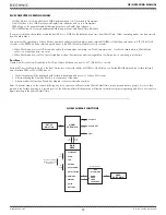
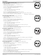
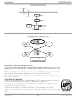
TRANSMITTER SIGNAL RECEPTION GUIDE
BEST
Reception
Area
Poor
Reception
Area
Poor
Reception
(when greater than 4 feet/1.2 meters)
Poor
Reception
Area
Poor
Reception
Area
Poor
Reception
Area
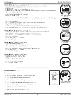
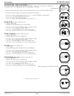
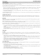
NORM DIVE MODE STRUCTURE
DIVE
MAIN
M
S
A
L
2 sec
< 2 sec
GAS/TMT
Switching
Backlight
2 sec
Safety Stop
Main
Deep Stop
Main
A
< 2 sec
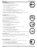
ALTs
A
< 2 sec
ALTs
ALTs
at
5 FT (1.5 M)
for 5 sec
at
2 FT (0.6 M)
for 1 sec
Surface Mode
Dive Mode
< 2 sec
ack Alarms
PROXIMITY OF THE TMTS (TRANSMITTERS) TO THE OCI
The TMTs emit low frequency signals that radiate out in semicircular patterns parallel to the length dimension of the TMT. A coiled
antenna inside the OCi receives the signals when it is positioned within a zone parallel to or at a 45 degree angle to the TMT as
illustrated.
The OCi cannot effectively receive a signal when it is held out to the sides of the TMT or held at distances greater than 4 feet (1.2
meters) in front of the TMT. Best reception is achieved when the OCi is within 3 feet (1 meter) of the TMT.
When installed into the high pressure ports of the Regulator First Stages, the TMTs must be positioned so that they face horizon-
tally outward from the Tank Valves.
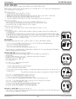
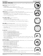
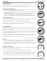
LINK INTERRUPTION UNDERWATER
During a dive, you may at times move the OCi out of the signal pattern of the TMT, resulting in a temporary loss of the Link sig-
nal. The Link will be restored within 4 seconds after the OCi is moved back into its correct position.
An interruption may also occur while the OCi is within 3 feet (1 meter) of a running DPV. The Link will be restored within 4
seconds after the OCi is moved out of that area.
A temporary interruption may also occur shortly after a Strobe fl ashes. The Link will be restored within 4 seconds.
If the Link is not restored within 15 seconds; the Audible will sound, and the graphic LOST, Pressure value, and Link icon will fl ash
(Fig. 62).
Fig. 62 - LOST LINK
Compass
Содержание OCi
Страница 1: ...1 OCi OPERATING MANUAL 2002 Design 2013 Doc No 12 5335 r02 9 12 13 OCi DIVE COMPUTER OPERATING MANUAL...
Страница 5: ...5 OCi OPERATING MANUAL 2002 Design 2013 Doc No 12 5335 r02 9 12 13 FEATURES AND FUNCTIONS...
Страница 11: ...11 OCi OPERATING MANUAL 2002 Design 2013 Doc No 12 5335 r02 9 12 13 WATCH MODE...
Страница 16: ...16 OCi OPERATING MANUAL 2002 Design 2013 Doc No 12 5335 r02 9 12 13 NORM SURFACE MODES...
Страница 28: ...28 OCi OPERATING MANUAL 2002 Design 2013 Doc No 12 5335 r02 9 12 13 DIVE MODE FEATURES...
Страница 33: ...33 OCi OPERATING MANUAL 2002 Design 2013 Doc No 12 5335 r02 9 12 13 NORM DIVE MODE...
Страница 40: ...40 OCi OPERATING MANUAL 2002 Design 2013 Doc No 12 5335 r02 9 12 13 NORM GAS TMT SWITCHING...
Страница 42: ...42 OCi OPERATING MANUAL 2002 Design 2013 Doc No 12 5335 r02 9 12 13 DIGITAL GAUGE OP MODE...
Страница 47: ...47 OCi OPERATING MANUAL 2002 Design 2013 Doc No 12 5335 r02 9 12 13 FREE DIVE TECH FREE DIVE OP MODES...
Страница 61: ...61 OCi OPERATING MANUAL 2002 Design 2013 Doc No 12 5335 r02 9 12 13 COMPASS MODE...
Страница 70: ...70 OCi OPERATING MANUAL 2002 Design 2013 Doc No 12 5335 r02 9 12 13 TECHNICAL DATA...
Страница 76: ...76 OCi OPERATING MANUAL 2002 Design 2013 Doc No 12 5335 r02 9 12 13 OCi DIVE COMPUTER OPERATING MANUAL...


