background image

Sauna & Steam

Oceanic Saunas  01902 450 550  sales

@oceanic-saunas.co.uk www.oceanic-saunas.co.uk

17

Sauna Heater Manual

10.8.  Insulation 

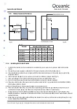
The door, ceiling and walls of sauna room must be insulated.  For every square meter of wall panel 

that is not insulated the size of cabin should decrease by 1.3 cubic meters in relation to the model 

of heater. Refer to table 1.

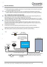
It is recommended to use a vapour barrier between timber panel and heating insulation.

Moisture and thermal proofing should be installed from outside to inside, such as:

i.  Recommend that the MIN thickness of the thermal insulation in the walls in 50mm and in the 

ceiling.

ii.  Aluminum foil laminate is affixed over the heating insulation as a moisture-proof. 

iii.  Leave at least 25mm air gap around the outside of the sauna cabin

iv.  Leave a 25mm gap between wall panel and ceiling to prevent gathering vapor.

10.9.  Air ventilation of sauna room 

•  Mix the cold air with hot air to relieve mugginess when bathing.

•  Draw the fresh air around the heater to ventilate the sauna room.

•  Move the warm air to the farthest part of sauna room using air vent at high level in the 

opposing corner to the heater

• 

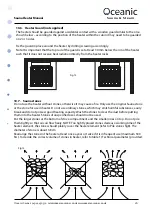
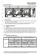
The inlet vent may be installed on the wall below the heater. (fig 15a).when using mechanical 

ventilation ,inlet vent is placed 50cm above the heater (fig 15b) or on the ceiling above the heater 

(fig 15c).the heavy cold air that blown into sauna room is mixed with the light not air from the 

heater ,bringing fresh air for bathers. The recommended inlet should have a diameter of 5—10cm.

The outlet vent should be placed diagonally opposite to the inlet. It is advised the outlet vent is 

placed under the platform in sauna room as far as possible from the inlet vent. It can be installed 

near the floor, or lead outside through a pipe from the floor going to a vent to the sauna ceiling, 

or under the door (to the wash room). In this case, the sill slot must be at least 5cm and it is 

recommended there is mechanical ventilation in washroom the size of the outlet should be twice 

of the inlet. 

 Warning: 

1. 

Switch off power during any maintenance, or fitting electrical units.

2. 

Do not hang clothes to dry in the heater, for this may cause a risk of fire.

3. 

Do not bake food in heater. 

4. 

When it is hot, the outer surface of the heater may burn your skin.

1.  Air supply vent

2.  Optional air supply vent if mechanical exhaust ventilation is used, the opening is located 50cm 

Содержание Apollo

Страница 1: ...PRODUCT IMAGE Oceanic Ltd Pountney Street Wolverhampton WV2 4HX Phone 01902 450 550 sales oceanic saunas co uk www oceanic saunas co uk Sauna Steam APOLLO SAUNA HEATER Assembly and operating manual ...

Страница 2: ... 3 2 Important Notes 3 3 Safety Precautions 3 4 Electrical connection 3 5 Specification 4 6 Sauna Heater and Control Box Circuit Diagrams 5 7 Sauna Heater Frame and Parts 8 8 OC SB Controller 10 9 Temp sensor frame and parts 12 10 Installation 12 11 Testing and Operation 18 12 Trouble shooting Guide 20 13 Maintenance 21 14 Warranty After Sales 22 ...

Страница 3: ...s used in an unsupervised and or public location with the advanced timer setting an interlock must be provided for the door 3 Safety Precautions Elderly persons pregnant women or these suffering heart disease high blood pressure diabetes or not in good health are advised to seek medical opinion before using a sauna room Do not smoke in the sauna room Avoid using the sauna room immediately after st...

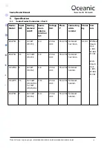
Страница 4: ... Connecting cable n mm2 Stones kg Size mm 0CAP30 3 3 1kW H1 H3 2 4 230 or 400 1N or 3N Terminal1 5 2 5mm 40 50 Without Steam Unit L 405 W 380 H 740 With Steam Unit L 495 W 380 H 740 0CAP45 4 5 3 1 5kW H1 H3 4 6 230 or 400 1N or 3N Terminal1 5 2 5mm OCAP60 6 6 1kW H1 H6 6 8 230 or 400 1N or 3N Terminal1 5x4mm OCAP75 7 5 3 1 5kW H1 H2 H4 3 x 1kW H3 H5 H6 7 10 230 or 400 1N or 3N Terminal1 5 6mm 0CAP...

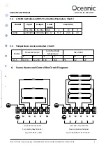
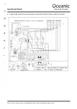
Страница 5: ...nd Control Box Circuit Diagrams Model Input Output Load power Size mm 1N 3N 1N 3N Kw L W H OCSB 230 400v 230 400v 4 5 12 310 260 70 Model Detected scope Cut off on high temperature Size mm o C o F o C o F L W H OC S 0 110 32 230 120 248 76 42 27 N N N N U U V V W W AC 230V 1N or 400V 3N AC 230V 1N or 400V 3N From control box Terminal From control box Terminal H1 H1 H2 H2 H3 H4 H3 H5 H6 Fig 1 a OCA...

Страница 6: ...Sauna Steam Oceanic Saunas 01902 450 550 sales oceanic saunas co uk www oceanic saunas co uk 6 Sauna Heater Manual i Fig 2a Circuit Diagram for OCSB control box wired with Single Phase 230V connection ...

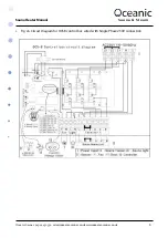
Страница 7: ...Sauna Steam Oceanic Saunas 01902 450 550 sales oceanic saunas co uk www oceanic saunas co uk 7 Sauna Heater Manual ii Fig 2b OCSB control box circuit diagram with wired with Three Phase 400V connection ...

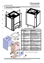
Страница 8: ...asket Holds sauna rocks 3 Central Body Contains Elements 4 Shell Insulate the inner shell to prevent from scalding 5 Terminal Connect the power supply 6 Power entry The route of power wires 7 Cover Panel Protects the electrical connections 8 Terminal plate Access to terminals 9 Mounting bracket To fix steam generator to heater central body 10 Feet Raise heater off ground 11 Under tray Collect exce...

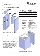
Страница 9: ...ove to access wiring terminal 9 Mounting bracket To fix steam generator to sauna heater 1 2 3 4 5 6 7 8 9 10 7 1 Steam Generator Diagram and Parts Fig 4a Steam Generator Part Diagram Chart 5 Steam Generator Part List Fig 4b Steam Generator Attachment 7 2 Fixing Steam Generator to Sauna Heater Note Steam Generator is an optional item and is not supplied with all Apollo Sauna Heaters For Apollo Heat...

Страница 10: ...oor interlock indicator LED Indicator LED is on Sauna Heater will not operate i e the door has been opened and the sauna must be checked for safe operation no towel over heater etc and door interlock reset before countdown timer can continue For commercial use only where a door interlock switch has been installed 14 High temperature LED indicator LED is on The sauna has overheated the room tempera...

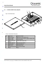
Страница 11: ...unction instruction 1 Wire anchorage Route of wire entry and fasten wires 2 Terminal block Connect to the mains power supply via isolator switch 3 Terminal block Connect to heater 4 Heater light and fan output Outlet to heater light and fan 5 Control cable entry The entry of control cable 6 Light terminal Connect to light wire 7 Fan terminal Connect to fan wire 8 Control panel terminal Connect to ...

Страница 12: ...fils the minimum requirements concerning the distances given in Fig 7 and chart 8 and allow for safety and convenience Is the controller box suitable for the heater power and control requirements Choose the cable wire according to table 1 and the cable wire can bear high temperature 170 oC it is recommended to use sillicon rubber cable wire Do not install more than one heater in a sauna room The h...

Страница 13: ...bove iv The minimum height of your sauna room must be 1900mm please refer fig 7a v The sauna heater is to stand on the level ground not on slatted floor mat vi Do not cover the sauna heater back with asbestos cement or similar material vii The wires which enter the sauna room must be rated to150o C type 60245 IEC 66 HO7RN F BSEN 6141 please refer to chart 1 viii Do not install two or more sauna he...

Страница 14: ...x to sauna heater or across the live terminals of on the heater The correct size heat proof cable is required to the heater from the control box This is not supplied as standard but can be bought at the required length from Oceanic Saunas Ltd or a local electrical wholesaler Sauna heater Control box light fan and temperature sensor connection drawing Optional Door interlock commercial use install ...

Страница 15: ... Fig 9 10 4 Installing the controller Control pad must be installed outside the sauna cabin Ideally the control box should be installed at a height of approximately 1200mm for ease of use Installation method Drill a 40mm diameter hole through the wall Pull the front off the keypad you may find it easier with a small flat electrical screw driver Pin the control cable 6 cores to the relevant ports I...

Страница 16: ...erwise it may cause a fire Only use the original Sauna stone or the stone for use in heater Do not use ordinary stones which may emit harmful substances easily break and do not possess good heating capacity Wash the stones to clear the dust before putting them into the heater Stones of unspecified sizes should not be used Put the larger stones at the bottom of stove compartment and the smaller one...

Страница 17: ...at high level in the opposing corner to the heater The inlet vent may be installed on the wall below the heater fig 15a when using mechanical ventilation inlet vent is placed 50cm above the heater fig 15b or on the ceiling above the heater fig 15c the heavy cold air that blown into sauna room is mixed with the light not air from the heater bringing fresh air for bathers The recommended inlet shoul...

Страница 18: ...se the elements and stones may smoke slightly and give off a smell please ensure the sauna cabin is well ventilated Connect to power supply press key temp and time windows will display data LED shows the sauna s heating status when the light is on the temperature of sauna room will rise and will achieve the preset temperature the default settings are 70 o C 158o F work time is 2 hours Chart 10 11 ...

Страница 19: ...desired setting is reached press MENU ENTER the window will stop flashing when it reaches 0 it will switch over to A Model and the heater will turn on Remember to set the time you want the heater on for on A Model before setting B Model For quick time adjustment hold the p or q and it will count continuously up or down when it reaches the time you want release and it will stop Temperature switch b...

Страница 20: ...hasn t been connected correctly 2 The high tempeature cut off switch is turned off 1 Check the connection to the temperature sensor 2 Check if the high temperature cut off switch is turned off i yes reset by hand Door LED is on During the advance timer countdown sequence the sauna room door has been opened the timing stopped and will not restart again until it is reset Reset counter down timer Wai...

Страница 21: ...intenance staff and detailed records kept For domestic use these checks should be carried out every 6 months Any obvious deterioration should be noted immediately if noticed in between maintenance checks and should be resolved before continuing use of the products Under no circumstances do we recommend operating the sauna cabin if any electrical wiring is considered to be hazardous please contact ...

Страница 22: ... that the benches in the sauna are wiped down with a weak solution of disinfectant and water after each use we especially recommend this in commercial divisions The floor in the sauna should be mopped regularly 14 Warranty After Sales All Oceanic Sauna Heaters are guaranteed for 12 months from the date of purchase against faulty materials or workmanship The guarantee excludes consumable items such...

Отзывы: