background image

TABLE OF CONENTS 


            PAGE


GENERAL DESCRIPTION

 ….................................  

1  


PRODUCT DATA AND SPECIFICATIONS

............  


UNIT DESCRIPTION


Standard Features..................................  


Applications / Operation..........................  


Electrical..................................................  

5  


Use of Extension Cords........................... 


Accessories………................................... 

7 - 12 


Options..................................................... 

13 


Installation................................................ 

14 


Electronic Controller................................. 

15 - 17 


SERVICE


Water Valve Adjustment, Unit Interior.....  

18 


Replacement Parts Procedure................. 

19 


Troubleshooting Guide............................. 

20 


Preventive Maintenance........................... 

21 


DIAGRAMS


Piping Schematic....................................... 

22 


Three Phase Monitor................................. 

23 


Wiring Diagrams......................................... 

24 - 29


FORWARD


This manual provides the user with basic details for the installation 
and operation of the Oceanaire Air Boss spot cooler.  It is recom-
mended to read and fully understand the instructions outlined within 
this manual, before operating the AQUACOOLER unit.   
 
As with all commercial air conditioning equipment, it is recommended 
to have the AQUACOOLER sized and installed by a licensed specify-
ing engineer and contractor, in accordance with all local and state 
codes.   The length of service received can be extended by following 
the installation and preventive maintenance instructions.  


NOTICE  


In our ongoing process of continuous improvement, the items and 
procedures described in this manual are subject to change without 
notice.  Please note model and serial number of the AQUACOOLER 
unit when contacting the factory.


Содержание OWC series

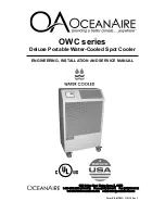
Страница 1: ...ENGINEERING INSTALLATION AND SERVICE MANUAL OWC series Deluxe Portable Water Cooled Spot Cooler Form EISM OWC 110114 Rev 1...

Страница 2: ...nd operation of the Oceanaire Air Boss spot cooler It is recom mended to read and fully understand the instructions outlined within this manual before operating the AQUACOOLER unit As with all commerc...

Страница 3: ...bjects through a dis charge grill located on the upper front of the unit while rejecting heat from the top of the unit The AQUACOOLER models range in cool ing capacities from 12 000 BTU HR to 60 050 B...

Страница 4: ...2...

Страница 5: ...ndensate tank is full and needs to be emptied In the 5 ton AQUACOOLER units model OWC60 CON indicates a condensate pump over flow condition where the pump is either disabled or incapable of rejecting...

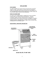
Страница 6: ...ACOOLER is it operates as a room air conditioner because water is used as the means for heat rejection The major convenience of water cooled air conditioning is the convenience of connecting water hos...

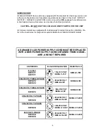
Страница 7: ...lity Re fer to the chart below for plug and receptacle details for all AQUACOOLER models A DAMAGED LCDI POWER SUPPLY CORD MUST BE REPLACED WITH A NEW POWER SUPPLY CORD OBTAINED FROM OCEAN AIRE AND NOT...

Страница 8: ...ED IT IS RATED AT LEAST 20 AMPS 250 VOLTS 3 PHASE FOR MODELS OWC6032 AN EXTENSION CORD MAY BEUSED PRO VIDED IT IS RATED AT LEAST 30 AMPS 250 VOLTS 3 PHASE FOR MODELS OWC3634 AND OWC6034 AN EXTENSION C...

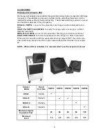
Страница 9: ...7 AQUACOOLER UNIT ACCESSORIES...

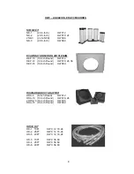
Страница 10: ...M DEP 10 10 Inch Round OWC12 DEP 12 12 Inch Round OWC18 24 36 DEP 16 16 Inch Round OWC60 DISCHARGE DUCT ADAPTER DDA 6 6 Inch Round OWC12 DDA 10 10 Inch Round OWC18 24 2DDA 16 16 inch Round OWC36 DDA 1...

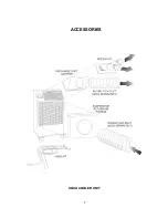
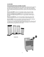
Страница 11: ...ximate extended length is 21 inches NK 2 for models OWC18 and OWC24 with 2 6 inch diameter nozzles with an approximate compressed length of 22 inches The approximate extended length is 32 nches 2NK 3...

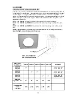
Страница 12: ...configuration and application information DEP 10 for OWC12 transitions the return air opening to a 10 inch round duct DEP 12 for OWC18 and OWC24 transitions the return opening to a 12 inch round duct...

Страница 13: ...verts the evaporator discharge to a 10 inch diameter round duct 2DDA 16 for OWC36 converts the evaporator discharge to a 16 inch round duct DDA 16 FOR OWC60 converts the evaporator discharge to a 16 i...

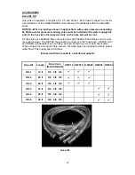
Страница 14: ...ose kits have FEMALE flare connectors to match the MALE flare fittings on the units see chart below The WATER IN connector consists of a 3 4 hose barb WATER OUT and DRAIN condensate have no fitting an...

Страница 15: ...ssure are avail able CUPRO NICKEL CONDENSER When chemically treated water salt water or brine is used in the conden ser coil it is recommended that the AQUACOOLER be equipped with a 90 10 Cupro Nickel...

Страница 16: ...cated on the back of the unit to make certain that the proper power is available for the unit Refer to Specifications section for voltage and amperage requirements For proper NEMA receptacles refer to...

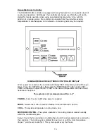
Страница 17: ...will then go blank Press the POWER button then press the TEMP SELECT button until the SET POINT is displayed Adjust the SET POINT to the desired temperature and the unit will heat cool as required Th...

Страница 18: ...d value is displayed 6 Use the MODE button to scroll through the programmable parameters P1 through P16 7 If no buttons are pushed the display will then return to the OFF position after about 50 secon...

Страница 19: ...urs 03 and 486 3486 hours 01 and 59 1059 hours TOTAL HOURS REPRESENTS COMPRESSOR RUN TIME MODEL CODE SETTINGS OWC12 P1 85 P2 35 OWC18 P1 80 P2 50 OWC24 P1 70 P2 50 OWC36 P1 85 P2 40 OWC60 P1 85 P2 45...

Страница 20: ...he water supply line In these cases it is recommended that the water valve be adjusted 1 Disconnect the unit power 2 Remove the unit back panel and locate the water regulat ing valve in the lower righ...

Страница 21: ...to locate the control box Disconnect wires and remove power module Install new power module and re wire in accordance with the wiring diagram C CONDENSATE PUMP ALL UNITS 1 Remove back panel and left...

Страница 22: ...MEDY Make sure set point is lower than room temperature Look for a red dot to the right of the temperature displayed for cooling Note there is a delay for the compressor CAUSE Thermostat Loose display...

Страница 23: ...hem in a solution of warm water and detergent for 10 minutes Then rinsing them clean with hot water and shaking excess moisture from filter CONDENSATE PUMP Condensate pumps come standard on all AQUACO...

Страница 24: ...22...

Страница 25: ...23...

Страница 26: ...24...

Страница 27: ...25...

Страница 28: ...26...

Страница 29: ...27...

Страница 30: ...28...

Страница 31: ...29...

Страница 32: ...accordance with the furnished written instructions or has been altered or modified in any way b to any expenses including labor or material incurred during removal or reinstallation of the Product c t...

Отзывы: