CS9360
INSTALLATION MANUAL
3 AP-40810_1.0
No.
Name
1
Transfer stays
2
Stand
No.
Name
3
Butterfly screws
1
2
3
4
Front
1
2
3
4
Front
1
2
3
4
Front
Front
1
2
3
3
2
1
1
1
2
1
1
1
2
2
2
3
3
3
3
3
3
1
2
3
4
5
3
1
1
2
2
1
2
1
No.
Name
1
Maintenance cover (Left)
No.
Name
2
Tray
2
3
1
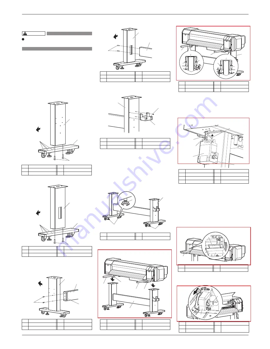
3 Assembling
This section explains how to assemble the printer.
3.1 Procedure for assembling the stand
Follow the procedure below to assemble the stand.
1. Follow the procedure below to assemble the right
stand.
a. Attach the right leg part to the right base part so
that four screw holes in the base part are at the
front.
b. Tighten two hexagon socket head cap screws using
a hexagonal wrench.
2. Assemble the left stand in the same way as in Step 1.
3. Fasten the connector bar to the right stand using
two hexagon socket head cap screws.
Attach the connector bar with the groove facing
the rear as shown below.
4.
Fasten the connector bar to the left stand in the
same way as in Step 3.
5. Attach the waste fluid tank holder to the right
stand using four screws.
6. Shake the stand to make sure that each part is firm-
ly attached.
3.2 Attaching the stand
Follow the procedure below to attach the stand to the
printer.
1. Turn the four adjusters as shown below to prevent
the stand from moving.
2. Insert the two transfer stays into the right and left
transfer brackets, lift the printer with four or more
people and place it on the stand.
3. Remove the two transfer stays and fasten the printer
to the stand using eight butterfly screws.
4. Follow the procedure below to attach the waste fluid tank.
a. Place the waste fluid tank in the waste fluid
tank holder.
b. Attach the waste fluid tube to the tank.
c. Insert the waste fluid sensor cable into the
connector on the bottom of the printer.
3.3 Detaching fastening materials
This product has fastening materials in the place
shown below.
Detach all protective materials in accordance with the
following steps.
1. Remove all tapes from each cover.
2. Open the left maintenance cover, then place the tray.
3. Open the front cover, then remove a screw from
the head unit fastening material (metal plate) and
remove the material.
No.
Name
1
Leg part (Left)
2
Base part
No.
Name
3
Hexagon socket head cap screws
4
Screw holes in base part
No.
Name
1
Adjusters
No.
Name
2
Stand
No.
Name
1
Waste fluid tank holder
2
Waste fluid tank
3
Waste fluid tube
No.
Name
4
Waste fluid sensor cable
5 Waste fluid sensor connector
No.
Name
1
Head unit
2
Screw
No.
Name
3
Head unit fastening
material (metal plate)
No.
Name
1
Stand (Right)
2
Connector bar
No.
Name
3
Hexagon socket head cap screws
4
Groove in connector bar
No.
Name
1
Stand (Left)
2
Connector bar
No.
Name
3
Hexagon socket head cap screws
No.
Name
1
Leg part (Right)
2
Waste fluid tank holder
No.
Name
3
Screws
No.
Name
No.
Name
1
Leg part (Right)
3
Hexagon socket head cap screws
2
Base part
4
Screw holes in base part
No.
Name
1
Transfer stays
2
Transfer brackets
No.
Name
3
Stand
CAUTION
Four or more people are required to
assemble this printer.


