background image

CS9200 Low Solvent series printers


53


AP-40301 – Rev. 2.0 – 02/05/2008


Adjustment procedure 

 
Please follow the instructions below to adjust the printer. 
 

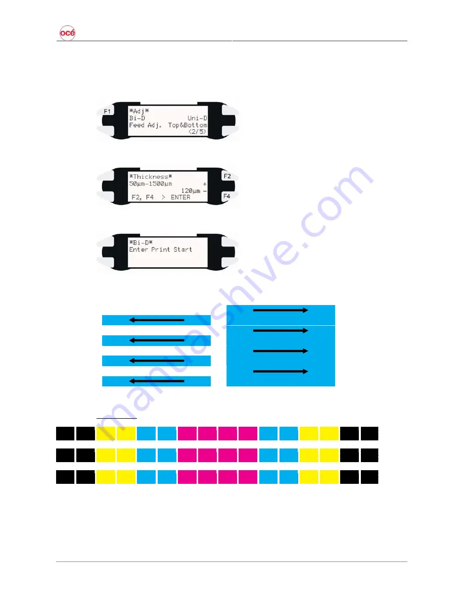
Step 1 : 

Print the first file 

 [Bi-D] 

 [F1] – key. 


Step 2 : 

Set the thickness of the media and press ENTER. 


Step 3 : 

Confirm with ENTER to start printing. 


Step 4 : 

Each nozzle row (1A, 1B, 2A, 2B …) will print 4 blocks from left to right and then 4 from right to 
left. 


First swath printed 

Second swath printed 

 
Final Pattern 


#3 ALL


#2 ALL


#1 ALL


8B 8A 7B 7A 6B 6A 5B 5A 4B 4A 3B 3A 2B 2A 1B 1A 


Содержание CS9265

Страница 1: ...Oc CS9265 Oc CS9290 Installation Guide Low Solvent...

Страница 2: ...CS9200 Low Solvent series printers 2 AP 40301 Rev 2 0 02 05 2008...

Страница 3: ...nsideration of the furnishing of the information contained in this document the party to whom it is given assumes its custody and control and agrees to the following The information herein contained i...

Страница 4: ...CS9200 Low Solvent series printers 4 AP 40301 Rev 2 0 02 05 2008...

Страница 5: ...4 3 Remove protective materials 28 4 4 Levelling the printer 29 4 5 Install the Unwinder Winder 100 31 4 6 Install the waste bottle 32 5 Connecting the cables 33 5 1 Connecting the foot switch 33 5 2...

Страница 6: ...xes Refer to chapter 3 3 Check in the box configuration Refer to chapter 2 4 Assemble the printer winder Refer to chapter 4 5 Connect the cables Refer to chapter 5 6 Load ink Refer to chapter 6 7 Load...

Страница 7: ...ENTS OF THIS MANUAL MAY BE CHANGED WITHOUT PRIOR NOTIFICATION OC TECHNOLOGIES HAS MADE THE BEST EFFORTS TO KEEP THIS PUBLICATION FREE FROM ERRORS IF YOU FIND ANY UNCERTAINTIES OR MISPRINTS PLEASE CONT...

Страница 8: ...CS9200 Low Solvent series printers 8 AP 40301 Rev 2 0 02 05 2008...

Страница 9: ...nvironment Temperature 23 C Humidity 55 without condensation Operational conditions for low solvent ink Temperature 20 C 30 C Humidity 40 to 65 without condensation Rate of change Temperature No more...

Страница 10: ...CS9200 Low Solvent series printers 10 AP 40301 Rev 2 0 02 05 2008 1 2 DIMENSIONS 1 2 1 CS9265 1 2 2 CS9290...

Страница 11: ...d are interchangeable Just ensure to have at one side of the printer at least 2 5 m This to be sure that you can pass with a roll of media 1 3 2 Required area For the CS9265 series Width x depth 0 6...

Страница 12: ...CS9200 Low Solvent series printers 12 AP 40301 Rev 2 0 02 05 2008...

Страница 13: ...NTS OF THE PACKAGES MAY BE DIFFERENT DEPENDING ON THE MARKET WHERE THEY ARE USED CONTACT YOUR LOCAL OC REPRESENTATIVE OR DISTRIBUTOR FOR DETAILS IF ANY PART IS MISSING OR BROKEN CONTACT EITHER OF THE...

Страница 14: ...CS9200 Low Solvent series printers 14 AP 40301 Rev 2 0 02 05 2008 2 1 CONTENTS UNIT BOX 2 2 CONTENTS PRINTER STAND BOX 1 2 Nr Description Qty 1 Stay 1 2 Foot 2...

Страница 15: ...ilips P2 1 2 Hexagon wrench 4 mm 1 3 Hexagon wrench 5 mm 1 4 Plain washer M6 16 5 Spring washer M6 16 6 Hexagon bolt M6x30 8 7 Hexagon bolt M6x16 8 8 Cable clamp 2 9 SCREWSET Tube clamp not used 3 10...

Страница 16: ...al kit 1 3 User and good shape kit 1 4 5 6 Ink starter set 1 2 4 1 Commercial kit 1 2 3 4 5 Nr Description Qty 1 User s Guide CS9200 Low Solvent series printer 1 2 CD with all manual in digital versio...

Страница 17: ...mber 29801288 Kit content Nr Description Qty 1 Sponge plate 6 2 Wipers 24 3 Spitting box sponge 12 4 Cleaning Liquid 250 ml 3 5 Instruction sheet 1 6 Good shape kit 1 Good shape kit order number 29801...

Страница 18: ...nt Cleaning Nr Description Qty Part number 1 Oc IJC920 HS Low Solvent Cleaning 8 29952255 2 4 5 Oc IJC920 HS Low Solvent ink Nr Description Qty Part number 1 Oc IJC920 HS Low Solvent ink Black 2 29952...

Страница 19: ...200 Low Solvent series printers 19 AP 40301 Rev 2 0 02 05 2008 2 5 CONTENTS UNWINDER WINDER 100 Notes PLEASE REFER TO THE USER S GUIDE OF THE UNWINDER WINDER 100 FOR THE COMPLETE IN THE BOX CONFIGURAT...

Страница 20: ...CS9200 Low Solvent series printers 20 AP 40301 Rev 2 0 02 05 2008...

Страница 21: ...G BOX ALWAYS REMOVE THE VINYL PLASTIC AND HOLD ON THE SIDE OF THE PRODUCT HOLDING THE UNIT OVER THE VINYL PLASTIC WRAPPING CAN RESULT IN SLIPPAGE AND DROPPING THE UNIT RESULTING IN DAMAGE 3 1 UNPACK T...

Страница 22: ...CS9200 Low Solvent series printers 22 AP 40301 Rev 2 0 02 05 2008 Step 3 Remove the 2 boxes stand and installation kit Step 4 Remove the top card board of the printer body Step 5 Remove the 3 buffers...

Страница 23: ...5 2008 Step 6 Remove the covering plastic Step 7 Prepare the printer to be installed on the stand Please refer to chapter 5 for all necessary information Flip open the box when using a forklift Cut aw...

Страница 24: ...s 24 AP 40301 Rev 2 0 02 05 2008 3 2 UNPACK THE STAND Step 1 Move the stand box to the location to unpack Step 2 Open the package Step 3 Remove the following items consecutively 1 Buffers 2 Stand 3 Bo...

Страница 25: ...STAND Assemble the stand according to the following procedure Step 1 Unpack the stand assembly as described in chapter 3 Step 2 Turn the stand upside down Step 3 Mount each foot to the stand Pay atte...

Страница 26: ...g procedure Step 1 Position the stand correctly with the PCB box screw holes to the right FRONT Step 2 Insert the lifting tubes in the brackets and tighten them with each two wing screws Step 3 Lift t...

Страница 27: ...t Step 6 Check if there is no gap between the body and the stand If there is a gap proceed to the next step If not tighten the eight screws Step 7 Insert 1 or more spacers between printer body and sta...

Страница 28: ...temporary buffers and brackets are installed on the printer Remove them before powering ON the printer 1 2 3 4 Step 1 Remove the protective film on the plexi front cover Step 2 Remove the two screws...

Страница 29: ...ition Step 2 Turn down all feet of the printer stand with an equal pressure until the wheels come off the ground Use a fork spanner SW 14 Step 3 Place the level on the right leg and level the printer...

Страница 30: ...ont cover Step 2 Place the level on the print platform Step 3 Adjust the levelling feet until the printer is completely level As for the example below higher or lower the left side or lower the right...

Страница 31: ...CS9200 Low Solvent series printers 31 AP 40301 Rev 2 0 02 05 2008 4 5 INSTALL THE UNWINDER WINDER 100 Notes Please refer to the User s Guide of the Unwinder Winder 100 for the proper installation...

Страница 32: ...er the four pre mounted screws and push it downwards Step 2 Tighten the four screws Step 3 Loosen the 2 waste tubes attached to the printer with some tape Step 4 Install the tubes at the top of the wa...

Страница 33: ...H BE AWARE OF THE FOLLOWING o DO NOT PLACE ANYTHING HEAVY ON THE FOOT SWITCH o DO NOT BEND THE CABLE OF THE FOOT SWITCH WITH FORCE AND DO NOT PULL o DO NOT PLACE THE FOOT SWITCH NEAR THERMAL DEVICES I...

Страница 34: ...VICE IS THE PLUG ON THE POWER SUPPLY CORD Caution BE CAREFUL OF THE FOLLOWING WHEN HANDLING THE POWER CABLE DO NOT MAKE ANY MODIFICATIONS TO THE POWER CABLE DO NOT PLACE ANYTHING HEAVY ON THE POWER CA...

Страница 35: ...N EARTH TERMINALS FOR TELEPHONE LINES OR LIGHTNING RODS DOING SO MAY CAUSE A LARGE FLOW OF VOLTAGE IF LIGHTNING OCCURS WATER PIPES OR FAUCETS IF THERE IS A PLASTIC PART IN THE PIPE THE EARTH WILL NOT...

Страница 36: ...EFER TO THE RECOMMENDATION MADE BY THE MANUFACTURER OF THE RIP SOFTWARE YOU HAVE SELECTED 5 3 2 Selecting cables This printer is compatible with following interfaces Centronics interface Network inter...

Страница 37: ...rinter to your computer follow the steps below Step 1 Power OFF the printer and your computer Step 2 Plug the cable connector of the interface cable into the interface connector at the back of the pri...

Страница 38: ...DATA3 To and from printer 22 SG 5 DATA4 To and from printer 23 SG 6 DATA5 To and from printer 24 SG 7 DATA6 To and from printer 25 SG 8 DATA7 To and from printer 26 SG 9 DATA8 To and from printer 27 S...

Страница 39: ...CONNECTOR TO THE INTERFACE BOARD HAVING DIFFERENT SPECIFICATIONS Step 1 Power OFF the printer Step 2 Plug the connector of the Ethernet cable into the connector of the network interface board at the b...

Страница 40: ...CS9200 Low Solvent series printers 40 AP 40301 Rev 2 0 02 05 2008...

Страница 41: ...OF OC IJC920 HS LOW SOLVENT INK AND CLEANING CASSETTES IF OTHER MANUFACTURERS PRODUCTS ARE USED THE OUTPUT QUALITY MAY BE INFERIOR FAINT OR INK ENDS MAY NOT BE PROPERLY DETECTED IF NON OC PRODUCTS AR...

Страница 42: ...r and moisten the rubber sides of the caps with Solvent Cleaning liquid when asked This to optimize the ink loading cycle Step 3 Close the front cover when done and press the ENTER key Step 4 Please w...

Страница 43: ...on the last page of the present document and follow further instructions a Remove the first cassette If the weight is higher than 270 gram not enough liquid has been pumped through the ink tube syste...

Страница 44: ...Solvent Cleaning liquid To verify proper behaviour a weight measurement of the cassettes has to be carried out Please fill in the document on the last page of the present document and follow further i...

Страница 45: ...l nozzles are present the first ink load procedure has been finished successfully Notes When you have used a syringe to complete the first ink load procedure it doesn t mean necessarily that there is...

Страница 46: ...CS9200 Low Solvent series printers 46 AP 40301 Rev 2 0 02 05 2008...

Страница 47: ...t media Step 4 When no media is loaded and the pressure rollers are raised the following message will be displayed the pressure rollers are lowered the following message will be displayed Step 5 Open...

Страница 48: ...entation F3 Width Media measurement sequence RIGHT LEFT TOP Media orientation Step 8 Close the front cover Step 9 Start media initialisation Menu Choice Description F2 Sheet Roll Select which kind of...

Страница 49: ...most important thing to know before adjusting is which nozzle row corresponds with which colour ink cassette head 1 2 3 4 5 6 7 8 HEAD 1 HEAD 2 HEAD 3 HEAD 4 HEAD 5 HEAD 6 HEAD 7 HEAD 8 1a 1b 2a 2b 3...

Страница 50: ...D SLANT CHECK Purpose of this check Check if the heads are positioned straightly How to print the file Power ON the printer in diagnostics mode Adjustment F2 HeadSlant F4 Slant F1 Pattern 8B 8A 7B 7A...

Страница 51: ...you only have to check if head 1 2 3 and 4 are in one line and the same for head 5 6 7 and 8 How to print the file Power ON the printer in diagnostics mode Adjustment F2 HeadSlant F4 F B F2 Pattern 1...

Страница 52: ...High Perform all 3 checks Bi D Standard Check Bi D400 Extra check for printing in FAST 540 Bi D480 Extra check for printing in FAST 360 How to print the files Bi D Power ON the printer in diagnostics...

Страница 53: ...rint the first file Bi D F1 key Step 2 Set the thickness of the media and press ENTER Step 3 Confirm with ENTER to start printing Step 4 Each nozzle row 1A 1B 2A 2B will print 4 blocks from left to ri...

Страница 54: ...rease or decrease all necessary bi dir values as follows a Select the head height in which you want to adjust the bi dir values b All nozzle rows 1A 1B 2A 2B will pass in order on the display If you d...

Страница 55: ...heck To check if each head fires at the same time compared with the reference head 1 How to print the files Power ON the printer in diagnostics mode Adjustment F2 Menu 2 4 Uni D F2 Pattern 1B 1A 1B 1A...

Страница 56: ...es FAST 720 FAST 540 or FAST 360 head 5 8 headset 2 have to be shifted 1 720 of an inch downwards compared with heads 1 4 headset 1 The pattern below will help you to fine tune this shift How to print...

Страница 57: ...visible result we recommend coated media Step 5 Edit the IP address in the PRINT BAT file in Notepad or Ultra edit 32 Step 6 Drag the file into the PRINT BAT file Be sure that the printer is connected...

Страница 58: ...ment screw Notes This image is only intended for visual support do not disassemble the heads Only loosen the two indicated screws Step 2 Tighten the screws 1 fixing head 5 8 Step 3 Print the file once...

Страница 59: ...ormal or powerful cleaning to regain all nozzles Prints a pattern to check if the distance adjustment step is set correctly If not you can change it easily Prints a list with important information reg...

Страница 60: ...heads are still well adjusted If necessary adjust the heads Please refer to the maintenance manual for all necessary information Prints the bi directional test pattern at 480 cps The purpose of this...

Страница 61: ...weekly maintenance 8 Change the wipers 9 Change upper sponge at the back of the capping station Monthly maintenance Available kits for the end user and their order numbers 1 User and good shape kit fo...

Страница 62: ...lying grease on the roller path carriage if needed 6 Applying grease on the capping station cam and gears if needed 7 Removing dust in the fan area underneath the print platform Every 6 months 8 Chang...

Страница 63: ...t which we would like you to fill in and send back to us Please fill in this form and mail fax it back to our service department Distributor Dealer and printer details Distributor Dealer Serial number...

Отзывы: