background image

Scanning

19

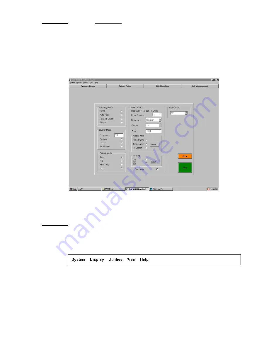
The Control window

When the Océ 3050 Microfilm Scanner Windows application is activated, the 
Control window appears on the screen. The following figure displays the 
default Control window.

[5] Default Control window

The different parts of this window are described in the following paragraphs.

The option bar

The option bar provides five pull down menus.

[6] The option bar

System  

This is a pull down menu which contains the exit route for terminating 

a scanning session.

Display  

This pull down menu selects one of the three possible display modes. 

All display modes are available during the scanning process and during the 

Содержание 3050

Страница 1: ...Oc 3050 User Manual...

Страница 2: ...Oc 3050 and the microfilm scanning that can be done with it The introduction chapter 1 contains a general description of the working methods for using the microfilm scanner and it is recommended that...

Страница 3: ...8 The Control window 19 The option bar 19 The selection buttons 20 The Control window 21 Scanning in Single mode 23 Cards with unknown Hollerith codes 23 Settings in the Control window 23 Scanning in...

Страница 4: ...l 58 Predefined File Name 68 Automatic Card Selection 70 The printer setup 72 Configuration 78 Chapter 6 File handling and administration The file handling setup 82 Scan data path 82 Process queue pat...

Страница 5: ...safe use 100 Safety data sheets 102 Safety data sheet Oc 3050 103 Appendix C Defining user defined file format User Defined file format 106 Header definition file 106 Header template file 108 Checking...

Страница 6: ...6 Oc 3050 User Manual...

Страница 7: ...7 Oc 3050 User Manual Chapter 1 Introduction This chapter contains a general description of the Oc 3050 Microfilm Scanner...

Страница 8: ...Scanner The Oc 3050 Microfilm Scanner is a table top machine which is controlled by the Oc 3050 Windows software running in the controlling PC The figures on the inside of the cover of this manual sho...

Страница 9: ...trolling PC as the cards are scanned The controlling software provides a zoom and pan facility to inspect the produced images carefully According to the control settings in the software 4 the Oc 3050...

Страница 10: ...g parameters before automatic scanning of a series of cards in BATCH mode AUTO FEED mode After a single card is fed and scanned as in SINGLE mode the next card is automatically fed after pressing the...

Страница 11: ...11 Oc 3050 User Manual Chapter 2 System installation This chapter informs you how to install the Oc 3050 Microfilm Scanner and the Oc 3050 Windows software...

Страница 12: ...and software requirements for running the Oc 3050 Windows softwar version 4 2 Minimum PC requirements Processor Pentium 4 2 8GHz or equalivent Memory 1 GByte RAM Hard Disk 40 GBytes Display 1024x768 p...

Страница 13: ...all the Oc 3050 software 1 Insert the Oc 3050 installation CD ROM in the disk drive of the PC 2 Run setup exe from the CD ROM 3 Now follow the instructions on the screen Preparing the PC for printing...

Страница 14: ...1 Open the Control Panel menu in Windows 2 Select Regional Settings 3 Specify the desired language in the Language selection box Note If you choose a language that is not supported English will be se...

Страница 15: ...ion 1 Switch the controlling PC on 2 Start Windows 3 With Windows running open the Oc 3050 Scanner Group 4 Double click the Oc 3050 icon The system starts up and performs a self test When the calibrat...

Страница 16: ...16 Oc 3050 User Manual 4 When the PC is shut down switch the ON OFF switch on the rear of the scanner to the O OFF position 5 Switch off the controlling PC if not already switched off automatically...

Страница 17: ...nual Chapter 3 Scanning This chapter gives an overview of the various parts of the Control window It also provides all necessary information to run a scanning session in Batch Single Auto Feed and Hol...

Страница 18: ...anner as shown in the illustration below Depending on the setting in the Configuration menu you must load the cards face up or face down see Configuration on page 78 4 Loading cards To load a batch of...

Страница 19: ...ol window The different parts of this window are described in the following paragraphs The option bar The option bar provides five pull down menus 6 The option bar System This is a pull down menu whic...

Страница 20: ...n selection buttons which are placed at the top of the Control window Each of these opens a setup dialogue box 7 The selection buttons Scanner setup Clicking the Scanner Setup button brings up the Sca...

Страница 21: ...ty Mode entry box is only accessible in Batch running mode This mode allows you to automatically pause the scanner after a preset number of scanned cards and to check the quality of the scanned images...

Страница 22: ...cted batch or single If Hollerith Naming is off depending of your choice File or Print File the following window appears before scanning starts 9 Image file name This window allows you to define the r...

Страница 23: ...Auto Feed mode you can add a string of Hollerith data to cards without Hollerith punches or with unknown Hollerith codes The special Hollerith Add Mode in the Configuration menu is designed for this...

Страница 24: ...in the input hopper of the scanner 7 Click the Start button to start the scanning 8 If required set the names for image files and log file see figures 9 and 10 on page 22 The system switches to the R...

Страница 25: ...that scanning can be performed automatically requiring your intervention only for loading and unloading stacks of cards Quality mode 11 Quality mode When using the Quality mode feature scanning proce...

Страница 26: ...ity mode Select the desired output mode of the Quality mode If you do not want a quality check take care the options buttons are empty not black not on 3 Select the Input Size or select Hollerith sizi...

Страница 27: ...duces the desired output In the View mode no output is generated Cards without Hollerith punches In Single and Auto Feed mode you can add a string of Hollerith data to cards without Hollerith punches...

Страница 28: ...rol settings as required 6 Place the aperture cards in the input hopper 7 Click the Start button to start the scanning session 8 If required set the names for image files and log file see figures 9 an...

Страница 29: ...ning controls in the Control window To start a scanning session in Hollerith Check mode 1 Click the Hollerith Check button in the Running Mode entry box 2 Select the Hollerith in the Input Size entry...

Страница 30: ...scanning is paused the Scanner Setup window can be called to change the imaging parameters and the drawing size of the scan In case a different display mode is preferred you can choose full enlarged...

Страница 31: ...selecting pause in stead of File Print Print File Reject This button rejects the scanned image No output is generated and the system returns to the Control window The card is ejected from the scanner...

Страница 32: ...area yourself Defining a new scanning area using the Frame option 1 Click the Frame button at the bottom of the screen The following window will appear 14 Frames window 2 Click on a standard frame si...

Страница 33: ...the bottom of the screen The area inside the defined frame will be rescanned Note To go back to the original image click Frame again The Frames window will disappear Then click Rescan to get the origi...

Страница 34: ...lay the images in three different modes The three display modes are available in the Display pull down menu They are described below Full Image This option provides a full screen display of the whole...

Страница 35: ...ng the zoom and pan facility The zoom ratio defines the level of detail of the image to be displayed and the pan position defines which part of the image is displayed The display area and zoom factor...

Страница 36: ...the Dual display consists of three subjects Cards Processed shows the number of cards already scanned in the batch and autofeed mode Scan Disk Usage is giving the disk capacity used and free capacity...

Страница 37: ...of the area to enlarge Dragging the mouse with the button still depressed defines a rectangular area The aspect ratio of this rectangle is the same as for the display window Releasing the left mouse...

Страница 38: ...38 Oc 3050 User Manual...

Страница 39: ...39 Oc 3050 User Manual Chapter 4 The Viewing mode...

Страница 40: ...y Click the View button in the option bar to enter the viewing function Click the Select option in the View pull down menu to open a file selection box showing all the file names of a specified type i...

Страница 41: ...screen 19 The View screen If more than one file is selected you can scroll to the next image the previous image auto after approx 3 seconds the next image appears automatically on the screen stop the...

Страница 42: ...e will be printed without zoom factor Print Enlarged Only the selected frame will be printed using a zoom factor to fill up the chosen paper format Leaving the View mode You leave the View mode by sel...

Страница 43: ...43 Oc 3050 User Manual Chapter 5 Setting up the Oc 3050 Microfilm Scanner This chapter explains how to set the configuration of the Oc 3050 Microfilm Scanner and peripherals...

Страница 44: ...onsists of five different cards Imaging Drawing Size Hollerith Control Predefined File Name Automatic Card selection Each card can be selected by clicking its label Besides these entry boxes the windo...

Страница 45: ...normal calibrated setting The normal setting is the optimum for all batch scanning and most other scanning but setting the LAMP BOOST parameter to a higher level increases the illumination on the fil...

Страница 46: ...t consequence of tracking the background density is that there is no means of distinguishing a large area of intentional foreground such as a logo block or inverse image area from a real change in bac...

Страница 47: ...low density as background and setting the POLARITY control to POSITIVE enables Image processing to work with positive images just as well as with negative images Switching to POSITIVE also inverts da...

Страница 48: ...e Imaging card 3 Click the Load button at the bottom of the Imaging card On pressing this button the following window is displayed 22 Loading an imaging setup All predefined setups are listed The exam...

Страница 49: ...ntry box 6 Click the Save button to add the new setup to the list To delete an imaging setup 1 Open the Scanner Setup window 2 Select the Imaging card 3 Click the Delete button The following window ap...

Страница 50: ...rawing Size card are described in detail below Drawing size Here you can select a specific drawing size from the drawing size file When selecting one of the drawing sizes the values for reduction rati...

Страница 51: ...d drawing sizes listed in the DWGSIZES DRG file You can define the input size reduction ratio drawing width and length and print size for your personal requirements 26 Drawing Size File After clicking...

Страница 52: ...ze card 3 Click the Edit File button to open the Edit Drawing Size File window 4 Click New Size 5 Enter a name for the new size in the upper right entry box 6 Choose the units to work with 7 Enter the...

Страница 53: ...only be altered manually when the NON STD size has been selected X and Y offsets This is the number of microns by which the image in the microfilm on the card is known to be off the centre of the fil...

Страница 54: ...le Any name up to 8 characters will do Units In this part of the window you can enter values in millimetres or inches Control buttons Resolution The resolution may be set to any value between 100 dpi...

Страница 55: ...on can be coded via the punches To understand the interpretation of the holes in the cards both the punches in the vertical direction column as in horizontal direction row must be explained see figure...

Страница 56: ...es in the horizontal direction row The interpretation of the numbers and characters in the horizontal direction row is company or project specific Every company had made the structure of the punched i...

Страница 57: ...h control file programming of it has to be done once how a company project specific card can be identified the so called card key on which positions the drawing number can be read file name on which p...

Страница 58: ...sizing Hollerith naming Control File 32 Hollerith Control card Hollerith sizing When this option is on the Hollerith reader in the scanner reads the information for the size of the scanned images fro...

Страница 59: ...on Hollerith sizing is automatically switched on Hollerith Naming however remains off Editing the Hollerith Control File When you click the Edit File button in the Hollerith Control entry box the Edit...

Страница 60: ...tore the Hollerith elements in a file first a filename for the Hollerith control must be defined 1 Insert the filename max 8 characters and the extension hcf in the filename entry box In this example...

Страница 61: ...lerith elements representing the key you have to follow this procedure 1 Click the Card Key radio button in the Display elements entry box see figure 33 on page 59 or see figure 34 2 Click New Card Ke...

Страница 62: ...n one Hollerith Control File No Card Key ALL_CARDS If no card key is used type ALL_CARDS in the Card Keys entry box Beware that all Hollerith elements are switched off Continue with inserting the file...

Страница 63: ...ndow see figure 38 2 In the Card Key list select the key you want to delete 39 Deleting a Card Key 3 Click Delete Card Key in the Card Keys window 4 Click Update to confirm and go back to the Scanner...

Страница 64: ...example of a card with the Hollerith elements representing the drawing number 12345678 of the microfilmed drawing in position 4 to 11 To insert the place of the Hollerith Elements of the filename most...

Страница 65: ...want to edit more in this window click Update later on To add a new Size Key Within a specific Hollerith structure different drawing formats are common The size key function will identify the various...

Страница 66: ...in the Display elements entry box 43 Hollerith Control File editing size keys 2 Click the New Size Key in the Size Keys entry box in this case type or look for A2 3 Choose in the Drawing Size a size...

Страница 67: ...ns or add specific drawing formats you first have to edit the drawing size file see section Edit drawing Size File on page 51 5 Select the other drawing format related elements in the Size Keys entry...

Страница 68: ...aming see Hollerith Control on page 58 the name of the file will be determined by the hollerith information Predefined File Name If you have not selected Hollerith Naming you can specify the file name...

Страница 69: ...first image Date Time If you select this option the root name will be followed by the numeric count the time and the date of scanning Log File Record If you select this option the root name will be f...

Страница 70: ...roughput of the scanning process 48 Automatic Card Selection card of the Scanner Setup window You can select the following operating modes Off All cards will be scanned Match Only if the Hollerith str...

Страница 71: ...anner 71 Specifying Automatic Card Selection 1 Open the Scanner Setup window 2 Select the Automatic Card Selection card 3 Specify one of the operating modes and select the ASCII file with Hollerith st...

Страница 72: ...ears 2 Select a printer from the list 3 Click Set Default Printer The name of the selected printer appears in the Default Printer box in the top of the Printer Setup window 4 Click OK to confirm your...

Страница 73: ...Type field the printer type belonging to the by Printer name Enter in the IP Address field the IP adress where the printer is connected When no IP Address is entered the Folder field will be used as o...

Страница 74: ...ill be used as output destination Enable the options the printer supports Enter in the RCF File name field the Standard RCF file which will be sent together with the scanned image to the printer Enter...

Страница 75: ...ed information by en disabling the options the printer supports Enter in the Folder field a local folder destination when you would like to store the scanned image to disk Press Ok to confirm or Cance...

Страница 76: ...below Use at your own risk BeginTicket OJT The contents of this file are inserted immediately after the BeginTicket command BeforeFiles OJT The contents of this file are inserted immediately be fore...

Страница 77: ...Copies 1 JobCollate on AccountId 0 UserId 0 BEFOREFILES OJT BeginBlock 1 InputSegment 1 BEGINBLOCK OJT Emulation auto ENDBLOCK OJT EndBlock BeginOutput IncludeBlock 1 BEGININCLUDEBLOCK OJT MediaType p...

Страница 78: ...tion The Start Up settings you can choose the factory settings for the system to start up or define your own start up settings The Machine Offsets the machine offsets are used to calibrate the machine...

Страница 79: ...n the disk to contain the image file The counter this counter can be reset to start from any number within the range 0 to 9999999 Proceed as follows to select the required start up settings To set you...

Страница 80: ...80 Oc 3050 User Manual...

Страница 81: ...81 Oc 3050 User Manual Chapter 6 File handling and administration...

Страница 82: ...n Data Path window you enter the path to the disk and directory for storing image data files They can be stored either locally in the controlling PC or on a different system in a network The path must...

Страница 83: ...ant byte of the binary header data is written in the higher memory address Use this option for PC With the Motorola option set the most significant byte of the binary header data is written in the low...

Страница 84: ...rmation Save Option You can select one of the following save options Scan Data If you want to store your images on disk select Scan Data All images will be stored in the directory that is specified as...

Страница 85: ...gement menu Maximum File Size This option sets the maximum size of a data file in MB If the specified file size is exceeded the card is automatically rejected if in Batch mode In Single or Auto Feed m...

Страница 86: ...ile is ON you are prompted for a log file name whenever a new scanning session is started File Name This entry defines the log file name Path This entry defines the log file path Note The log file pat...

Страница 87: ...contains the same information but for rejected scans only Print Clicking this button prints the LOG FILE or the REJECT FILE currently specified In order to print the contents of the LOG file or REJ fi...

Страница 88: ...Hollerith information of the card The name of this file will be the same as the name of the image file but the extension will be HOL Single Line Record If you select this option all information of ea...

Страница 89: ...89 Oc 3050 User Manual Chapter 7 Maintenance and troubleshooting This chapter contains all information on clearing card jams It also explains how to clean the scanner drum...

Страница 90: ...clear the card jam by clicking the Clear button in the Control screen Scanning can proceed if the card is ejected into the output hopper If this does not work you should remove the card manually Proc...

Страница 91: ...l clockwise to remove the card The position of the thumb wheel is shown in the illustration below 60 Thumb wheel The card slides upwards as you turn the wheel in the direction indicated by the arrow 3...

Страница 92: ...cedure window appears on the screen 61 Clean Drum 3 Open the scanner access door Caution Make sure your tie or hair is not hanging over the scanner as it may get caught when the drum starts rotating 4...

Страница 93: ...93 Oc 3050 User Manual Appendix A Technical specifications...

Страница 94: ...reyscale No Hoppers Input type Auto Input capacity 250 Output Accept 250 Output Review No Output Reject No Digital Microfilm Printing No Production Tools Framing manual Yes Cropping manual Yes Deskew...

Страница 95: ...none no greyscale Check print capability Yes Viewing facility Yes Internal graphical diagnostics Yes Agency approvals CE TUV UL cUL EMC CE FCC Voltage two ranges 90V 132V or 180V 264V Operating syste...

Страница 96: ...el to return to the Printer Connect dialogue box IDS_MSG16 Printer Setup cannot be changed during scanning IDS_MSG17 File Handling parameters cannot be changed during scanning IDS_MSG18 Specified scan...

Страница 97: ...ase fan the cards in the Input Hopper and press Retry to continue cancel returns to the Con trol screen IDS_MSG1103 Card edge detection failure IDS_MSG1104 Card failed to feed out of the machine IDS_M...

Страница 98: ...name or path IDS_MSG1124 Image data file failed to open Please check the filing directory IDS_MSG1125 Disk usage exceeded The filing hard disk or the print spool directories have reached the percentag...

Страница 99: ..._CARDS Cards Processed IDS_SBOX_MB MBytes IDS_SBOX_NOS Nos Prints IDS_SBOX_PRINT Print Queue Status IDS_SBOX_SCAN Scan Disk Usage IDS_SBOX_SIZE Size IDS_SBOX_USED Used IDS_STATUS_AUTOFEE D Autofeed ID...

Страница 100: ...100 Oc 3050 User Manual...

Страница 101: ...99 Oc 3050 User Manual Appendix B Safety information...

Страница 102: ...oint has the right fuse capacity See the Oc 3050 safety data sheet in this appendix for information about maximum current Do not bridge any mechanical or electrical circuit breakers Do not use an exte...

Страница 103: ...about space and ventilation requirements General Always use materials recommended by Oc and developed for this Oc machine Materials not approved by Oc may result in faults in your machine Do not use...

Страница 104: ...to the best of our knowledge as a compact guide to safe handling of this product We reserve the right to revise safety data sheets as new information becomes available It is the user s responsibility...

Страница 105: ...tion 100 W Power consumption standby 100 W Mains connection Cable with plug Safety class I IEC 536 Protective earth connection Protection class IP 20 IEC 529 Sound pressure level At operator position...

Страница 106: ...104 Oc 3050 User Manual...

Страница 107: ...pendix C Defining user defined file format This appendix gives an description of the procedure to define the User Defined file format It informs you about the contents of the Header Definition file an...

Страница 108: ...Header Definition file which defines the image dependent data records tobe written into each image file header The Header Defenition file will always be called USER DEF It will always be found in the...

Страница 109: ...te As default Padding Character space is used Note As default Data Format string is used Note Constant from the corresponding record in the Header Template file Note Pointer in bytes to the start of t...

Страница 110: ...rmat string Length 57 Offset 13 Data hollerith Record_1 Padding Character 0 Data Format string Length 6 Offset 82 Data length Record_2 Padding Character 0 Data Format string Length 6 Offset 99 Data wi...

Страница 111: ...able characters and CR LF characters However non printable characters may also be used Separator characters may be used or omitted depending onthe user s requirements Hollerith is 12345678901234567890...

Страница 112: ...eated file Checking the created Header Definition file 1 Start the Oc 3050 application 2 Scan a Hollerith card to file 3 Open an editor 4 Open the scanned file with the defined extension in the editor...

Страница 113: ...111 Oc 3050 User Manual Appendix D Miscellaneous...

Страница 114: ...ollowed by a series of numbered steps that take you step by step through all phases of performing the operation Figures and tables Figures and tables are titled and numbered sequentially throughout th...

Страница 115: ...y and arrangement page layout chapter order etc Yes No Could you find the information you were looking for Always Most of the times Sometimes Not at all What did you use to find the required informati...

Страница 116: ...completed by Even if you prefer to remain anonimous please fill in your occupation Name Occupation Company Phone Address City Country Please return this sheet to Oc Technologies B V To the attention...

Страница 117: ...ING SIZE 50 E EDITING HOLLERITH CONTROL FILE 61 67 HOLLERITH DATA 31 NEW DRAWING SIZE 52 ERROR MESSAGES 95 EXIT 19 F FILE FORMAT 83 FILE NAME PREDEFINED 68 FORMAT FILE 83 FRAME 32 FREQUENCY SEE QUALIT...

Страница 118: ...ME DISPLAY 30 S SAFETY DATA SHEETS 102 SAFETY INFORMATION 100 SCAN WINDOW 53 SCANNING AUTO FEED MODE 27 BATCH MODE 26 HOLLERITH CHECK MODE 29 SINGLE MODE 23 SCANNING AREA 32 SELECTION AUTOMATIC CARD 7...

Страница 119: ...Index 117...

Отзывы: