15
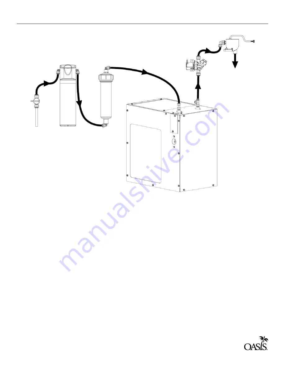
Chiller
Optional In-Line
Filter
Optional
Versafilter III
Inlet Ball Valve
Assy. with
Strainer
Solenoid
Valve
In
Out
UV-C LED
A.
B.
C.
D.
E.
F.
G.
H.
Plumbing rough-in and wall opening should be prepared as shown in the rough-in
drawing. This drinking water cooler is designed to be operated at a water supply line
pressure of up to 100 PSI (690 kPa). A pressure regulator must be installed in front of the
unit’s water inlet if the pressure (including any possible pressure spikes) could exceed 100
PSI (690 kPa).
Assemble the optional inline filter clip to the chiller in the location shown on PAGE:
Install stem elbows (provided) on the in-line filter and place in the in-line filter in the
previously installed clip.
Mount the VersaFilter III in the location shown on page 15 and install the stem elbows
provided.
Install 1/4” union fittings (provided) on the chiller unit inlet and outlet water lines.
Install provided 3/8” O.D. copper tube, strainer, ball valve and reducer to the building
water supply.
Install the water tubing as shown above.
Note the tubing from the chiller outlet fitting to the solenoid valve inlet fitting should be
insulated (provided). The tubing from the solenoid valve outlet fitting to the UV-C LED inlet
fitting should also be insulated.
STEP 3: FILTER INSTALLATION (WITH CHILLER)


