background image

CAUTION

READ AND SAVE THESE INSTRUCTIONS

A patient safety strap is required during all procedures. Follow normal and required safety protocol for all procedures 

where the patient is in an elevated position for the procedure (straps, attendants, etc.). Always be certain that attending 

staff is aware of the patient’s position while the device is in use. Reposition the patient if necessary to promote stability. 

Due to the increased distance between the patient and the table surface, additional safety measures are recommended 

when the table top is not used in a level position due to the risk of the patient falling off the table.
The Oakworks® Spine Positioning System II is not designed for use with diagnostic x-ray systems where the x-ray 

generator is located above the radiographic table and the film cassette or image intensifier is located below the radio-

graphic table. The X-Ray generator must be located below the radiographic table. The Spine Positioning System II is not 

designed for use with magnetic resonance imaging systems. The Spine Positioning System II is not intended for use in 

cranial procedures.
Do not overhang the radiolucent frame beyond the warning line on the frame.
Operate the C-arm of the fluoroscopy system with the Spine Positioning System II in place before using the device with 

a patient for the first time. Make sure there is adequate clearance to permit free C-arm rotation for both the patient and 

the positioning device.
Do not permit the patient to push down on the Crescent Face Pad in an effort to lift themselves up while dismounting the 

platform and/or the table.
The Spine Positioning System II should generally not be used when a patient is under general anesthesia, especially 

when prolonged cases are performed. This will reduce the risk of ocular or facial nerve injury.
The cushioning foam contained within the Torso Support will lose its ability to spring back to the original position over 

time and the amount of foam compression will increase. Therefore, the Torso Support should be replaced periodically to 

ensure the device functions as intended. 
To prevent the potential of cross-contamination, it is strongly advised to use barrier techniques when the device is 

in use. A disposable or laundered patient gown, or disposable pad are satisfactory for use as a barrier for the Torso 

Support and other components and accessories, except when the patient presents with pathology that would indicate 

otherwise. A disposable face rest cover should be used to cover the Face Rest Pad. Contact Oakworks for ordering 

information. Barrier techniques should be used in addition to disinfection procedures, not in lieu of them.
Be sure to support the weight of the patient’s head while making adjustments to the cervical positioning feature of the 

Platform Frame. Make sure all cam locks are secure before relinquishing support of the positioning assembly. 

DANGER

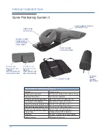
The Cervical Support System has metal parts that can cause back scatter of x-rays, see Product Description for photo. 
When x-rays are present, wear a suitable radiation barrier.
The Spine Positioning System II is constructed using metal pins in the Quick Cam Locks and aluminum tubing in the 

support structure. These are out of the field of view in most A-P and oblique tilted views. Place the positioning assembly 

according to the recommendations in the directions for use to eliminate, or reduce any artifacts. If artifacts still remain 

to the extent that they would compromise the efficacy of needle placement, discontinue use of the device during the 

affected procedure.
The Spine Positioning System II is designed to be a standalone product used with radiographic equipment. It must not 

be modified or incorporated into any other equipment. 
All materials used in the construction of the device and accessories are safe for temporary and moderately frequent 

human contact. The device is not intended for prolonged contact.
Do not use the Face Rest Support Arms as a handle to carry the Spine Positioning System II. 


Follow maintenance instructions found near the end of this manual. Mechanical components should be checked periodi-

cally to insure that they are functioning properly to insure the safety of the patient. 

SPS II weight limit: 350 lbs. (159 kg.) Crescent Face Pad Support weight limit: 25 lbs. (11 kg.)

IMPORTANT SAFETY INSTRUCTIONS

2

IMPORTANT SAFETY INSTRUCTIONS

Содержание Spine Positioning System II

Страница 1: ...OAKWORKS Imaging and Pain Management Accessory Spine Positioning System II USER MANUAL www oakworksmed com 717 235 6807...

Страница 2: ...within this document is subject to change without notice and should not be construed as a commitment by OAKWORKS Inc OAKWORKS Inc encourages requests for technical specifica tions and the like documen...

Страница 3: ...orso Wedge 5 Large Adjuster Pad 5 Small Adjuster Pad 5 8 20 cm Semi Round Bolster 5 Directions for Use Preparation for Use 6 Face Rest Platform Adjustment 6 Torso Support Strap 7 Transporting the Spin...

Страница 4: ...rpose of aiding in patient positioning and comfort during non surgical imaging or spinal injection procedures It may also be used during minimally invasive surgical procedures such as vertebroplasty o...

Страница 5: ...ons as intended To prevent the potential of cross contamination it is strongly advised to use barrier techniques when the device is in use A disposable or laundered patient gown or disposable pad are...

Страница 6: ...x 22 x 2 20 x 56 x 5 cm Small Rectangular Adjuster Pad 7 x 12 x 1 5 18 x 30 x 4 cm 8 20 cm Semi Round Bolster 6 x 8 x 26 15 x 20 x 66 cm Carry Case Transports the SPS II System Warranty 2 years Frame...

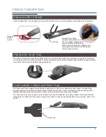
Страница 7: ...moved in situations to prevent imaging of the locking mechanism when performing upper cervical procedures that require substantial imaging angulation CONTOURED TORSO SUPPORT PAD The Contoured Torso S...

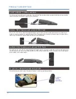
Страница 8: ...descend out of the plane of the cervical and thoracic spine This pad offers a wide range of flexibility for general patient positioning and stabilization LARGE RECTANGULAR ADJUSTER PAD The wider 8 x 2...

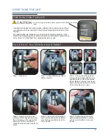
Страница 9: ...STMENT Step 1 Open cam Step 2 Grasp platform and raise to desired position Step 3 Line up the locking pins on the leg with the handle with the corre sponding holes on the center pieces Minor platform...

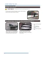
Страница 10: ...y Case put some pads wedges or bolsters on both sides of the base frame Spine Positioning System Radiolucent Frame Spine Positioning System Pads Spine Positioning System Pads DIRECTIONS FOR USE WARNIN...

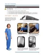
Страница 11: ...approach cervical procedures Components used Radiolucent Frame Crescent Face Pad Contoured Torso Support Pad Contoured Torso Wedge Small Adjuster Pad 8 Semi Round Bolster not pictured SPS II set up f...

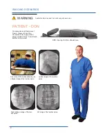
Страница 12: ...ound Bolster not pictured Don in the SPS II while obtaining an oblique image of the lumbar spine Right oblique image of the lum bar spine Lateral image of the lumbar spine AP image of the lumbar spine...

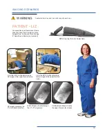
Страница 13: ...II while obtaining an AP image of the upper thoracic spine Lateral image primarily through the C7 T2 segments AP image visualizing the T1 2 interlaminar space Contralateral oblique showing the upper...

Страница 14: ...s AP image through the C1 2 joints Components used Radiolucent Frame Crescent Face Pad Contoured Torso Support Pad Contoured Torso Wedge 7 x 12 Rectangular Adjuster Pad 8 Semi Round Bolster not pictur...

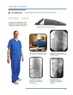
Страница 15: ...or planning the trajectory for a left thoracic facet injection Right thoracic oblique image to visualize the trajectory for a transfo raminal injection Contralateral oblique showing the trajectory for...

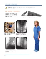
Страница 16: ...set up for Debbie shown here Debbie in the SPS II while obtaining a lateral cervical image AP image of the cervical spine while imaging through the C7 T1 interlaminar space Contralateral oblique of th...

Страница 17: ...er the target interspaces Lateral collimated image of the cervical spine The C6 7 T1 interspaces are appre ciated for all posterior approach cervical procedures such as interlaminar epidural steroid i...

Страница 18: ...procedure Because of possible chemical incompatibilities between various cleaning products and bleach utmost care must be taken by the user to avoid potential exposure to harmful or toxic by prod uct...

Страница 19: ...kly Use the following procedure Step 1 Lock the platform cam Step 2 Rock platform up down Gently rock platform up and down and note any looseness some flexing is normal Look for gaps between the alumi...

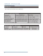
Страница 20: ...rso Wedge 70 mm 100 kVp HVL of 3 6 mm 22 x 29 x 2 56 x 74 x 5 cm Small Adjuster Pad 35 mm 100 kVp HVL of 3 6 mm 7 x 12 x 1 5 18 x 30 x 4 cm Large Adjuster Pad 35 mm 100 kVp HVL of 3 6 mm 8 x 22 x 2 20...

Страница 21: ...th the torso pad Model Name Unique Device Information GTIN 14 digit number unique for each variation of a model Manufacture Date Country of manufacture and date the device goes into production in YYYY...

Страница 22: ...THIS PAGE IS INTENTIONALLY LEFT BLANK 19...

Страница 23: ...20 THIS PAGE IS INTENTIONALLY LEFT BLANK...

Страница 24: ...nt Accessory Spine Positioning System II USER MANUAL CONTACT INFORMATION CoYoMe b v CoMedical Edisonsraat 2 4 3284 WD Oud Beijerland The Netherlands www coyome eu Enrico Cohen Enrico coyome nl info co...

Отзывы: