background image

8

IMAGING SCENARIOS

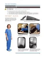
PATIENT - ALICIA

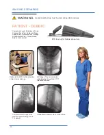
Demonstrates the generous amount 

of space under the head/face while 

laying comfortably in the SPS II

Alicia in the SPS II while obtaining  

a C3 pillar view

Right C3 and C4 pillar view of Alicia. 

The target articular pillars are visual-

ized for posterior approach facet/

medial branch procedures.

Lateral view of the cervical spine. The 

C2-3 to C7-T1 interspaces are easily 

visualized for all posterior approach 

cervical procedures.

Components used: Radiolucent Frame,  

Crescent Face Pad, Contoured Torso  

Support Pad, Contoured Torso Wedge,   

Small Adjuster Pad, 8” Semi-Round 

Bolster (not pictured)

SPS II set up for Alicia shown here

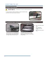
WARNING

IMAGING SCENARIOS

A patient safety strap must be used during all procedures.

The following imaging scenarios of patients will demonstrate:
1.  Various body types using the Spine Positioning System II (SPS II)

2.  Their positioning and specific configurations of the SPS II used in particular clinical situations

3.  Various fluoroscopic images of these factitious patients that exemplify the value of the SPS II

Содержание Spine Positioning System II

Страница 1: ...OAKWORKS Imaging and Pain Management Accessory Spine Positioning System II USER MANUAL www oakworksmed com 717 235 6807...

Страница 2: ...within this document is subject to change without notice and should not be construed as a commitment by OAKWORKS Inc OAKWORKS Inc encourages requests for technical specifica tions and the like documen...

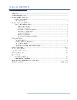
Страница 3: ...orso Wedge 5 Large Adjuster Pad 5 Small Adjuster Pad 5 8 20 cm Semi Round Bolster 5 Directions for Use Preparation for Use 6 Face Rest Platform Adjustment 6 Torso Support Strap 7 Transporting the Spin...

Страница 4: ...rpose of aiding in patient positioning and comfort during non surgical imaging or spinal injection procedures It may also be used during minimally invasive surgical procedures such as vertebroplasty o...

Страница 5: ...ons as intended To prevent the potential of cross contamination it is strongly advised to use barrier techniques when the device is in use A disposable or laundered patient gown or disposable pad are...

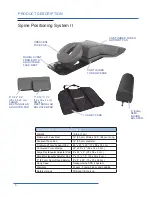
Страница 6: ...x 22 x 2 20 x 56 x 5 cm Small Rectangular Adjuster Pad 7 x 12 x 1 5 18 x 30 x 4 cm 8 20 cm Semi Round Bolster 6 x 8 x 26 15 x 20 x 66 cm Carry Case Transports the SPS II System Warranty 2 years Frame...

Страница 7: ...moved in situations to prevent imaging of the locking mechanism when performing upper cervical procedures that require substantial imaging angulation CONTOURED TORSO SUPPORT PAD The Contoured Torso S...

Страница 8: ...descend out of the plane of the cervical and thoracic spine This pad offers a wide range of flexibility for general patient positioning and stabilization LARGE RECTANGULAR ADJUSTER PAD The wider 8 x 2...

Страница 9: ...STMENT Step 1 Open cam Step 2 Grasp platform and raise to desired position Step 3 Line up the locking pins on the leg with the handle with the corre sponding holes on the center pieces Minor platform...

Страница 10: ...y Case put some pads wedges or bolsters on both sides of the base frame Spine Positioning System Radiolucent Frame Spine Positioning System Pads Spine Positioning System Pads DIRECTIONS FOR USE WARNIN...

Страница 11: ...approach cervical procedures Components used Radiolucent Frame Crescent Face Pad Contoured Torso Support Pad Contoured Torso Wedge Small Adjuster Pad 8 Semi Round Bolster not pictured SPS II set up f...

Страница 12: ...ound Bolster not pictured Don in the SPS II while obtaining an oblique image of the lumbar spine Right oblique image of the lum bar spine Lateral image of the lumbar spine AP image of the lumbar spine...

Страница 13: ...II while obtaining an AP image of the upper thoracic spine Lateral image primarily through the C7 T2 segments AP image visualizing the T1 2 interlaminar space Contralateral oblique showing the upper...

Страница 14: ...s AP image through the C1 2 joints Components used Radiolucent Frame Crescent Face Pad Contoured Torso Support Pad Contoured Torso Wedge 7 x 12 Rectangular Adjuster Pad 8 Semi Round Bolster not pictur...

Страница 15: ...or planning the trajectory for a left thoracic facet injection Right thoracic oblique image to visualize the trajectory for a transfo raminal injection Contralateral oblique showing the trajectory for...

Страница 16: ...set up for Debbie shown here Debbie in the SPS II while obtaining a lateral cervical image AP image of the cervical spine while imaging through the C7 T1 interlaminar space Contralateral oblique of th...

Страница 17: ...er the target interspaces Lateral collimated image of the cervical spine The C6 7 T1 interspaces are appre ciated for all posterior approach cervical procedures such as interlaminar epidural steroid i...

Страница 18: ...procedure Because of possible chemical incompatibilities between various cleaning products and bleach utmost care must be taken by the user to avoid potential exposure to harmful or toxic by prod uct...

Страница 19: ...kly Use the following procedure Step 1 Lock the platform cam Step 2 Rock platform up down Gently rock platform up and down and note any looseness some flexing is normal Look for gaps between the alumi...

Страница 20: ...rso Wedge 70 mm 100 kVp HVL of 3 6 mm 22 x 29 x 2 56 x 74 x 5 cm Small Adjuster Pad 35 mm 100 kVp HVL of 3 6 mm 7 x 12 x 1 5 18 x 30 x 4 cm Large Adjuster Pad 35 mm 100 kVp HVL of 3 6 mm 8 x 22 x 2 20...

Страница 21: ...th the torso pad Model Name Unique Device Information GTIN 14 digit number unique for each variation of a model Manufacture Date Country of manufacture and date the device goes into production in YYYY...

Страница 22: ...THIS PAGE IS INTENTIONALLY LEFT BLANK 19...

Страница 23: ...20 THIS PAGE IS INTENTIONALLY LEFT BLANK...

Страница 24: ...nt Accessory Spine Positioning System II USER MANUAL CONTACT INFORMATION CoYoMe b v CoMedical Edisonsraat 2 4 3284 WD Oud Beijerland The Netherlands www coyome eu Enrico Cohen Enrico coyome nl info co...

Отзывы: