background image

Instruction Manual 


CON 11/110 


38

8.2 

P1.0: Unit Configuration (COF) 

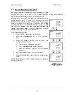
8.2.1  P1.1: Selection of READY and Auto HOLD function 

Program P1.1 gives you an option to on or off the “READY” display which indicates 
the measurement stability during a measuring process.  
Program P1.1 also gives an option to activate the Auto 
HOLD function (Only for CON 110). Activating the auto 
HOLD function lets the meter to “hold” your measurement 
when it is stable for more than 5 seconds. The display 
automatically freezes, and HOLD indicator appears on the 
left side of the display. Press the HOLD key to release the 
display and access other functions. Deactivate the auto 
HOLD function if you do not want this feature. 
From measurement mode 

Press SETUP key to enter Set Up menu.  

2  Press the HOLD/ENTER key to view parameter 

P1.1.  

3  Press the MI/

 or MR/

 keys to select the 

configuration you require.  


“ON” activates the READY function. 


“OFF” deactivates the READY function. 

  “ON” and “HOLD” activates the Auto HOLD 

function. 

Press HOLD/ENTER key to confirm selection. 

Press the CAL/MEAS key to return to measurement 
mode.  

NOTE: Meter default is set for Ready function on, and auto 
HOLD function off.  

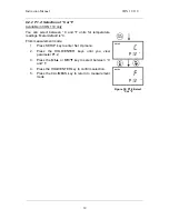
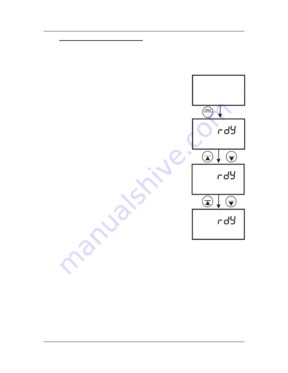
SETUP

READY

ON

p 1.1

SETUP

cof

p 1.0

SETUP

READY

OFF

p 1.1

SETUP

READY

HOLD

ON

p 1.1

MI

MI

MR

MR

ENTER

Figure 31: P1.1-

Configure READY ON, 

OFF or HOLD


Содержание CON 110

Страница 1: ...Instruction Manual CON 11 CON 110 Handheld Conductivity TDS Temperature RS232C Meter Technology Made Easy 68X361303 Rev 2 01 04...

Страница 2: ...er please do not hesitate to contact the nearest Authorised Distributor Eutech Instruments Oakton Instruments cannot accept any responsibility for damage or malfunction of the meter caused by improper...

Страница 3: ...version Factor 18 4 7 3 Calibrating for TDS using TDS standards 19 5 MEASUREMENT 20 5 1 AUTOMATIC TEMPERATURE COMPENSATION 20 5 2 MANUAL TEMPERATURE COMPENSATION 21 5 2 1 Setting the manual temperatur...

Страница 4: ...ORTABLE DAS FOR CON 110 ONLY 53 9 1 SYSTEM REQUIREMENTS 53 9 2 LOADING CYBERCOMM PORTABLE DAS 53 9 3 RUNNING CYBERCOMM PORTABLE 59 9 3 1 Buttons Check Box 60 9 3 2 Menu 61 9 3 3 Communication Settings...

Страница 5: ...es of the discerning individual You have one of the two models CON 11 meter CON 110 meter Your meter includes a conductivity electrode ECCONSEN91W electrode constant K 1 0 with built in temperature se...

Страница 6: ...17 18 mS ppt ppm S K Figure 1 Active LCD display 1 SETUP Setup mode indicator 7 ppt Parts per thousand indicator 13 Electrode indicator 2 MEAS Measurement mode indicator 8 ppm Parts per million indic...

Страница 7: ...ta during memory recall MI MR MI Memory Input Captures the measured readings of the Conductivity or TDS with its corresponding temperature values and stores them in the memory MR Memory Recall Retriev...

Страница 8: ...ion Manual CON 11 110 4 MODE MEAS CAL ENTER HOLD MR MI SETUP RANGE OFF ON MI MR SETUP MODE MEAS CAL ENTER HOLD OFF ON RANGE Keypad for CON 11 meter Keypad for CON 110 meter Figure 2 CON 11 and CON 110...

Страница 9: ...he procedure outlined below 1 Open the battery compartment by pressing down the catch of the battery cover 2 Insert the batteries correctly according to the marked polarity of the battery compartment...

Страница 10: ...m 2 Polybutylene Terephthalate PBT Valox 3 Stainless Steel SS 304 Proper use of electrode is essential to ensure that the optimum measurement is taken in a short time The removable protective plastic...

Страница 11: ...ale connector on the meter Rotate the locking ring clockwise until it locks 2 To remove the electrode simply rotate the connector s locking ring counterclockwise and pull away gently for a complete re...

Страница 12: ...in different positions 3 4 1 Inserting the electrode into the electrode holder The holder is designed for electrodes 16 mm in diameter Electrodes larger than 16 mm may not fit in the holder Forcing t...

Страница 13: ...witch on the power source of the adapter followed by the meter 3 6 Connecting the RS232C Cable Only for CON 110 The CON 110 meter provides an RS232C output for you to transmit your readings either to...

Страница 14: ...ESCRIPTION 1 2 Transmit Data 3 4 5 CTS Clear to Send 6 7 GND Ground 8 9 A one to one connection can be made with a 9 pin RS232C port of the computer 1 2 6 3 7 4 8 5 9 In case CON 110 meter s output ha...

Страница 15: ...00 to 17 00 mS 1 00 to 9 99 ppt 3 00 to 8 50 ppt 20 0 to 199 9 mS cm 60 0 to 170 0 mS 10 0 to 99 9 ppt 30 0 to 170 0 ppt Table 1 Recommended Calibration Solution Range in correspond to Conductivity T...

Страница 16: ...calibrate the meter at least once a week to get good accuracy If you are measuring in the mid ranges and you wash the electrode in deionised water and store it dry calibrate the meter once a month If...

Страница 17: ...tory default calibration 4 Dip the electrode into a solution of known temperature i e a temperature bath Allow time for the built in temperature sensor to stabilise 5 Scroll with the MI or MR keys to...

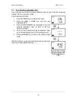
Страница 18: ...dure The known calibration standards used for automatic calibration are Meter Temperature Normalisation tnr C Calibration Standards Range 25 0 C 84 S for 0 200 S cm 1413 S for 0 2000 S cm 12 88 mS for...

Страница 19: ...electrode into the calibration standard Immerse the electrode tip beyond the upper steel band Stir the electrode gently to create a homogeneous sample Allow time for the reading to stabilise 4 Press...

Страница 20: ...ution whose value is outside the tolerance range For instance For 1413 S conductivity calibration standard 40 tolerance is from 848 S to 1978 S 2 All new calibration data will over ride existing store...

Страница 21: ...te a homogeneous sample Allow time for the reading to stabilise 4 Press CAL MEAS key to enter conductivity calibration mode The CAL indicator will appear in the upper corner of the display The upper p...

Страница 22: ...ctory default setting for TDS conversion factor is 0 5 If your solution has a different TDS factor you can improve calibration accuracy by setting the TDS factor prior to calibration 1 Press MODE key...

Страница 23: ...de 1 If necessary press the MODE key to select the TDS mode 2 For the rest of the calibration process repeat the similar step 2 to 6 as in the section of Manual Calibration on page 17 this time using...

Страница 24: ...ht on the LCD NOTE If the conductivity TDS electrode is not properly attached to the meter or it has been damaged the ATC indicator will blink and the temperature display will show Ur If the ATC indic...

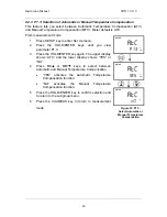
Страница 25: ...annunciators of C and ATC or F and ATC 3 Press the HOLD ENTER key again The upper display shows ATC and the lower display shows YES 4 Press the MI or MR key to select the lower display to show NO 5 P...

Страница 26: ...display 3 While in conductivity or TDS calibration mode press the MODE key to enter temperature calibration mode The primary display act as the adjustable temperature setting and the secondary displa...

Страница 27: ...stabilise Note the reading on the display 5 Press the MODE key to toggle between conductivity and TDS readings 5 3 1 Taking measurements with READY indicator selected on If the READY indicator has be...

Страница 28: ...indicating the range you are in The range selected will appear on the display and the MEAS indicator blinks indicating that you are in manual range 2 Press the range key again if needed until desired...

Страница 29: ...old a measurement press the HOLD ENTER key while in measurement mode HOLD will appear on the display 2 To release the held value press the HOLD ENTER again Continue to take measurements NOTE If the me...

Страница 30: ...mory MEM StO and memory number will appear for a moment after which the meter then returns to measurement mode 2 If necessary measure the next sample solution and press MI key to input the next data i...

Страница 31: ...Press HOLD ENTER key again to return to the memory location screen The display automatically moves to the next memory location screen 4 If necessary press the MI or MR keys to select the next memory l...

Страница 32: ...Flow Control None Please refer to your printer s or computer s instruction manual for more information on its communication setup protocol 3 Use 9 pin cable Refer to section List OF Accessories on pa...

Страница 33: ...current data automatically based on the pre set timing from 5 to 30 seconds 2 dAt StO Prints stored data from memory This function lets you print all the memorised data from memory previously stored...

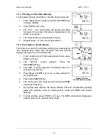
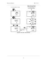
Страница 34: ...from 5 to 30 seconds 1 From conductivity or TDS measurement mode press PRINT key 2 The dAt Cur screen appears Press the HOLD ENTER key 3 The SEC 5 screen appears The default value is 5 seconds time in...

Страница 35: ...t mode data will be printed on pre set timed interval To stop press PRINT key ENTER HOLD ENTER HOLD MI MR Set timed interval for printing eg every 10 seconds MEAS MEM READY 2 1 0 1 4 1 3 C Flash for 0...

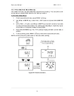
Страница 36: ...tored data This setting gives flexibility to match the meter to a printer s or computer s ability to accept data 4 Press HOLD ENTER key The Prn primary display will flash until all data is printed 5 T...

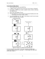
Страница 37: ...y The meter is now ready to recall the next stored data in the following memory location During measurement mode Repeat print procedure or press CAL to exit For example select memory location 10 Last...

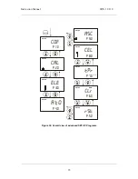
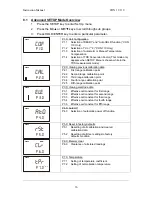
Страница 38: ...ferent sub groups that organise setup parameters The sub groups are 1 P1 0 Unit Configuration COF 2 P2 0 Viewing previous calibration data CAL 3 P3 0 Viewing electrode data ELE 4 P4 0 Auto Power OFF A...

Страница 39: ...SETUP P6 0 C E L SETUP P8 0 A s c SETUP P9 0 SETUP P7 0 SETUP P5 0 MI MI MI MR MR MR MI MR SETUP MEM P1 0 SETUP C A L P2 0 SETUP E L E P3 0 SETUP C O F P4 0 MI MI MI MR MR MR SETUP A o C F Figure 30 O...

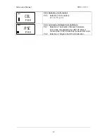
Страница 40: ...econd range calibration point P2 3 Third range calibration point P2 4 Fourth range calibration point P2 5 Fifth range calibration point SETUP E L E P3 0 P3 0 Viewing electrode data P3 1 Effective cell...

Страница 41: ...tion of cell constant K 1 0 10 or 0 1 A s c SETUP P9 0 P9 0 Automatic and Single Point Calibration P9 1 Selection of Automatic or Manual Calibration This mode only appears when SETUP Menu is chosen wh...

Страница 42: ...Press the HOLD key to release the display and access other functions Deactivate the auto HOLD function if you do not want this feature From measurement mode 1 Press SETUP key to enter Set Up menu 2 P...

Страница 43: ...fault is C From measurement mode 1 Press SETUP key to enter Set Up menu 2 Press the HOLD ENTER keys until you view parameter P1 2 3 Press the MI or MR key to select between C and F 4 Press the HOLD EN...

Страница 44: ...ss the HOLD ENTER key again The upper display shows ATC and the lower display shows YES or NO 4 Press MI or MR keys to select between Automatic and Manual Temperature Compensation YES activates the Au...

Страница 45: ...1 Press SETUP key to enter Set Up menu 2 Press the HOLD ENTER keys until you view parameter P1 4 3 Press the HOLD ENTER key again The upper display shows a value and the lower display shows tdS 4 Pre...

Страница 46: ...s the HOLD ENTER key repeatedly to view the previous calibration data on each of the five measuring ranges 4 Once you have scrolled through all calibration data you will automatically return to the su...

Страница 47: ...MI or MR keys until you view parameter P3 0 3 Press the HOLD ENTER key repeatedly to view the effective cell constant for each range 4 When you have scrolled through all the electrode data you will a...

Страница 48: ...you view parameter P4 0 3 Press the HOLD ENTER key The upper display shows AtO and the lower display shows YES or NO 4 Press MI or MR keys to select options YES activates the Auto Off function NO dea...

Страница 49: ...hanged are not reset From measurement mode 1 Press SETUP key to enter Set Up menu 2 Press the MI or MR keys to until you view parameter P5 0 3 Press the HOLD ENTER key to enter parameter P5 1 with the...

Страница 50: ...pper display will show USr 4 Press the HOLD ENTER key again to enter user reset selection mode 5 Press the MI or MR keys to toggle between NO and YES NO retains current settings YES resets to factory...

Страница 51: ...r Set Up menu 2 Press the MI or MR keys until you view the parameter P6 0 3 Press the HOLD ENTER key to enter parameter P6 0 4 Press the MI or MR keys to toggle between NO and YES NO retains current m...

Страница 52: ...SETUP key to enter Set Up menu 2 Press the MI or MR keys until you view parameter P7 0 3 Press the HOLD ENTER key to select parameter 7 1 The display shows tCO on the upper display 4 Press the HOLD EN...

Страница 53: ...MR keys until you view parameter P7 0 3 Press the HOLD ENTER key three times to select display tnr at parameter P7 2 4 Press the HOLD ENTER key again The upper display shows the normalisation temperat...

Страница 54: ...h your meter has a cell constant of K 1 0 From measurement mode 1 Press SETUP key to enter Set Up menu 2 Press the MI or MR keys until you view parameter P8 0 3 Press the HOLD ENTER key to enter param...

Страница 55: ...applicable in both conductivity and TDS mode Only from the conductivity measurement mode 1 Press SETUP key to enter Set Up menu 2 Press the MI or MR keys until you view parameter P9 0 3 Press the HOLD...

Страница 56: ...ual calibration mode the calibration factor would only be applicable in the particular range where the calibration is done 1 Press SETUP key to enter Set Up menu 2 Press the MI or MR keys until you vi...

Страница 57: ...re this redundant processing can be eliminated or reduced 9 1 System Requirements To run the DAS program the following is required 1 PC IBM Compatible XT and above with CD ROM Drive 2 EGA Monitor and...

Страница 58: ...Instruction Manual CON 11 110 54 Figure 47 Click on Browse button and locate CD ROM drive Figure 48 Locate the CyberComm Portable Setup program in the CD ROM under Eutech DAS directory...

Страница 59: ...Instruction Manual CON 11 110 55 Figure 49 Select Portable Meters directory to go to CyberComm Portable Figure 50 Open CyberComm Portable to enter to the Setup program...

Страница 60: ...Instruction Manual CON 11 110 56 Figure 51 Select SETUP EXE program and click the OPEN button Figure 52 InstallShield Wizard dialog box appears Figure 53 Click on Next button...

Страница 61: ...Manual CON 11 110 57 Figure 54 Key in your name and company name and click NEXT button Figure 55 To select another Destination Directory to install the program click on BROWSE button Otherwise click...

Страница 62: ...Instruction Manual CON 11 110 58 Figure 56 Creating a new program folder Click on NEXT button Figure 57 Click on NEXT button...

Страница 63: ...H button to end installation 9 3 Running CyberComm Portable Before running the DAS program please ensure that the RS232 cable is connected between the computer s serial port and the meter s port See s...

Страница 64: ...ion Click this button to enable communication between meter and computer 2 Clear Readings To clear all data and start all over again 3 Save Readings To save all data displayed in either dat or txt for...

Страница 65: ...email address and updates are shown 9 3 2 Menu 1 Communication Settings To set communication port number baud rate speed parity and stop bits protocol 2 Open To open previously saved data file 3 Save...

Страница 66: ...ng CON 110 Meter with Printer or Computer on page 28 for the settings 9 3 3 Communication Settings 1 Connect Using For selecting communication port Select 1 2 Baud Rate For selecting baud rate Select...

Страница 67: ...ing the RS232C Cable Only for CON 110 page 9 for connection procedure 2 Switch on the CON 110 meter and run the Data Acquisition software 3 Click ENABLE CONNECTION button 4 With the CON 110 meter swit...

Страница 68: ...een the Data Acquisition program and the meter The COM port number in the Data Acquisition program is wrong Change the COM port number 1 or 2 in the Data Acquisition program Your computer s COM port s...

Страница 69: ...he electrode thoroughly by stirring it in a mild detergent bath or isopropyl alcohol Wipe the electrode with a soft tissue paper Rinse thoroughly in tap water and then in de ionised water Recalibrate...

Страница 70: ...unciator Wrong keypad input Wrong input in selected mode Release key Select valid operations depending on mode Secondary Display Toggles Continuously between Calibration Standard Values Calibration er...

Страница 71: ...by nearby electric motor e Electrode guard not attached a Tap electrode to remove bubbles move electrode away from bubbles is present in sample b Clean the electrode and re calibrate c Make sure sampl...

Страница 72: ...NSEN91W 35608 50 2 platinum rings Epoxy body Electrode with ATC Cell Constant K 0 1 EC CONSEN72W 35608 55 2 platinum rings Epoxy body Electrode with ATC Cell Constant K 10 0 EC CONSEN73W 35608 51 Carr...

Страница 73: ...1 00 P3 2 Effective cell constant for second range Viewing Only Viewing Only K 1 00 P3 3 Effective cell constant for third range Viewing Only Viewing Only K 1 00 P3 4 Effective cell constant for fourt...

Страница 74: ...K 1 00 P3 2 Effective cell constant for second range Viewing Only Viewing Only K 1 00 P3 3 Effective cell constant for third range Viewing Only Viewing Only K 1 00 P3 4 Effective cell constant for fou...

Страница 75: ...200 F to 230 F Temperature Accuracy 0 5 C 0 5 C 0 9 F Cell Constant K 0 1 1 0 10 0 Selectable 0 1 1 0 10 0 Selectable Temperature Compensation Automatic Manual from 0 to 100 C Automatic Manual from 0...

Страница 76: ...Display Custom Dual LCD Custom Dual LCD Power Requirements 4 AAA Batteries 4 AAA Batteries AC DC Adapter ratings I P Voltage range 9 to 15V Current rating 200 mA I P Voltage range 9 to 15V Current ra...

Страница 77: ...ve a built in temperature sensor If you use a different electrode without a temperature sensor you must measure the solution temperature separately and manually enter the solution temperature see manu...

Страница 78: ...Wait for 5 minutes Note T1 and CT1 conductivity at T1 9 Condition the sample solution and electrode to a temperature T2 that is about 5 C to 10 C different from T1 and note the conductivity reading C...

Страница 79: ...omer Unauthorised modification or misuse Operation outside of the environment specifications of the products 20 RETURN OF ITEMS Authorisation must be obtained from our Customer Service Department or a...

Страница 80: ...ruments P O Box 5136 Vernon Hills IL 60061 USA Tel 1 888 462 5866 Fax 1 847 247 2984 E mail info 4oakton com Web sites www 4oakton com www oaktoninstruments com Eutech Instruments Pte Ltd Blk 55 Ayer...

Отзывы: