


Page
4
of
22
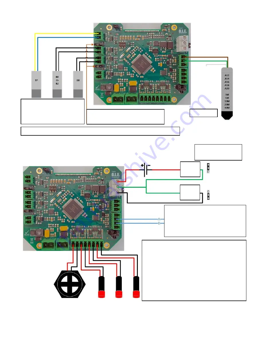
Input Connections
Output Connections
RS485 / MODBUS RTU
or
USB Programmer
A = Orange (Old Programmer = Yellow)
B = Yellow (Old Programmer = Blue)
Level Probe
Note: Jumper needs to be on Enable
for High Level and / or Bund Alarm
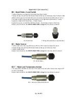
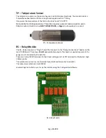
TP = Temperature Probe
B8 or B2 = High Level probe or
water bottom sensor
B8 = Bund Probe
Configurable Alarm Outputs
All are Switchable Supply Voltage.
M = Master Alarm, set 95% Rising and can be
acknowledged from the front panel.
B = (Bund or Water Bottom) Alarm also acknowledged
from the front panel
1,2,3 are additional Alarms.
1 = 90% Rising, 2 = 10% Falling, 3 = 5% Falling.
These are factory set on request or with the
Configuration Kit / lead by the end user.
Passive
mA
Loop
mA
OUTPUT
–
Analogue 4-20mA
Passive
–
Externally Powered
Loop
–
Powered by T5020
Reed switch used in B8 and B2 probes: Rating 10w / Switching Voltage 0.5A 240VAC
Содержание T4020
Страница 1: ...O L E UK Ltd T4020 T5020 INSTRUCTION INSTALLATION MANUAL Revision 02 Date 26 03 2017 PD02 0002 ...
Страница 14: ...Page 13 of 22 Appendix 1 T5020 Wiring Diagram ...
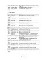
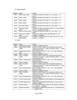
Страница 15: ...Page 14 of 22 Appendix 2 Modbus Register Table ...
Страница 16: ...Page 15 of 22 ...
Страница 17: ...Page 16 of 22 ...
Страница 18: ...Page 17 of 22 ...


