


Page
10
of
22
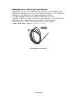
Click on the
Tank Settings
tab.
The next step is to set the tank shape up. Enter the tank type from the scroll down menu, a name for the tank
and the measurements.
Ensure that the Enable 4-20mA Output is ticked.
Please make sure the Mirror Output
box is NOT ‘Checked’ (ticked).
If it is we need to discuss.
The Mirror input may be used when a second Gauge is set exactly the same as the first. Alternatively, the
second Gauge can be set to have the Sensor Parameters the height of the primary tank and this will work over
the full 4-20 milliamp range of the first gauge output. No sensor offset required.
When this screen is complete, Click
Write Settings.
Click on the
Alarm Setpoints
tab.
Set the Alarm settings as required (High is normally 95% Rising).
Set the “Direction” to “Rising” or “Falling”. This will result in energising the R
elays (R5 Option Board) if fitted
in that ‘form’.
Rising at 95% on the M alarm will output 24vdc when the level increases to 95%.
When this screen is complete, Click
Write Settings
.
Note: that the tank can be taller than the
sensor range due to specific gravity.
For example, the tank being 2.2m tall. If we say
this is Diesel (DERV), then 2.2 x 0.835 = 1.837
affective range on the sensor. This means we
can use a 2.0m sensor in a 2.2m tank.
A 3.0m sensor will work fine as well
Содержание T4020
Страница 1: ...O L E UK Ltd T4020 T5020 INSTRUCTION INSTALLATION MANUAL Revision 02 Date 26 03 2017 PD02 0002 ...
Страница 14: ...Page 13 of 22 Appendix 1 T5020 Wiring Diagram ...
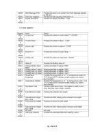
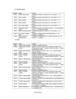
Страница 15: ...Page 14 of 22 Appendix 2 Modbus Register Table ...
Страница 16: ...Page 15 of 22 ...
Страница 17: ...Page 16 of 22 ...
Страница 18: ...Page 17 of 22 ...


