


NXP Semiconductors
UM11036
Point of Sales (POS) Reader Solution - Quick Start Guide
UM11036
All information provided in this document is subject to legal disclaimers.
© NXP Semiconductors N.V. 2017. All rights reserved.
User manual
COMPANY PUBLIC
Rev. 1.2 — 7 February 2017
406512
46 of 56
4.4 Hardware Modifications
Chapters 4.4.1 and 4.4.2 describe board modifications on TWR-POS-PN5180 and TWR-
POS-K81 boards allowing download of PN5180 Firmware.
POS kits delivered after 8 February 2017 already include these changes.
4.4.1 TWR-POS-PN5180 Board Modification
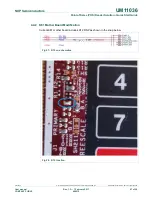
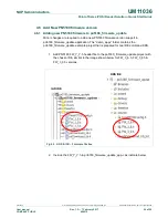
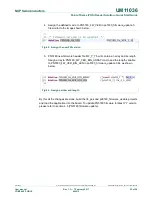
Current TWR-POS-PN5180 board includes NC (Non Connected) R41 as shown in below
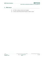
schematic. Add 0 Ohm resistor in place of “R41 NC”. See the below board image to
identify the R41 resistor placing.
Fig 55. R41 on schematics
Fig 56. R41 location