


NXP Semiconductors
UM11758
UJA1169A evaluation boards
3 Connecting the UJA1169Ax-EVB into a CAN network
The following conditions must be met before powering up the system with a 12 V supply.
•
Connect all boards in the ECU to a common GND
•
Connect SPI pins to the MCU SPI master:
–
SDO (J3-03, J4-09) → MISO
–
SDI (J3-04, J4-07) → MOSI
–
SCK (J3-05, J4-11) → SCK
–
SCSN (J3-06, J4-05) → CS
•
Connect TXD/RXD (J3-01/J3-02, J4-18/J4-20) pins to the MCU CAN controller TXD/
RXD pins
•
Connect RSTN (J3-09/J5-05) to the MCU CAN controller reset pin
•
Connect CANH and CANL (J1-01/J1-02) to the CAN bus twisted-pair cables
•
Connect V1(J3-08, J5-03) to the MCU supply unit
•
For the UJA1169AXF-EVB, connect VEXT (J3-10) to the peripheral loads that need a
5 V supply (optional)
Once the above steps have been completed, the ECU/EVB can be powered up using an
external battery supply. The UJA1169A starts up in Forced Normal mode (if MTP is not
configured) or Standby mode (if MTP configured), awaiting commands from the MCU via
the SPI interface.
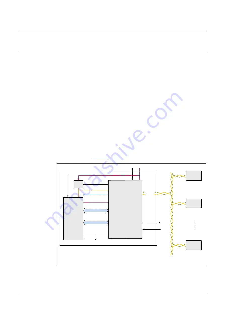
An example showing how to connect the UJA1169AXF-EVB between an MCU and the
aaa-045590
ECU A
TXD/RXD
V1
CANH
GND
12 V
CANL
LIMP
GND
ECU X
ECU B
ECU N
WAKE
RST
VEXCTRL/VEXCC
VEXT
SPI
PNP
MCU
UJA1169AXF-EVB
Figure 15. Connecting the UJA1169AXF-EVB into an ECU/CAN bus network
UM11758
All information provided in this document is subject to legal disclaimers.
© NXP B.V. 2022. All rights reserved.
User manual
Rev. 1 — 19 April 2022
15 / 39