


TWR-K70F120M Tower Module User's Manual
Page 14 of 25
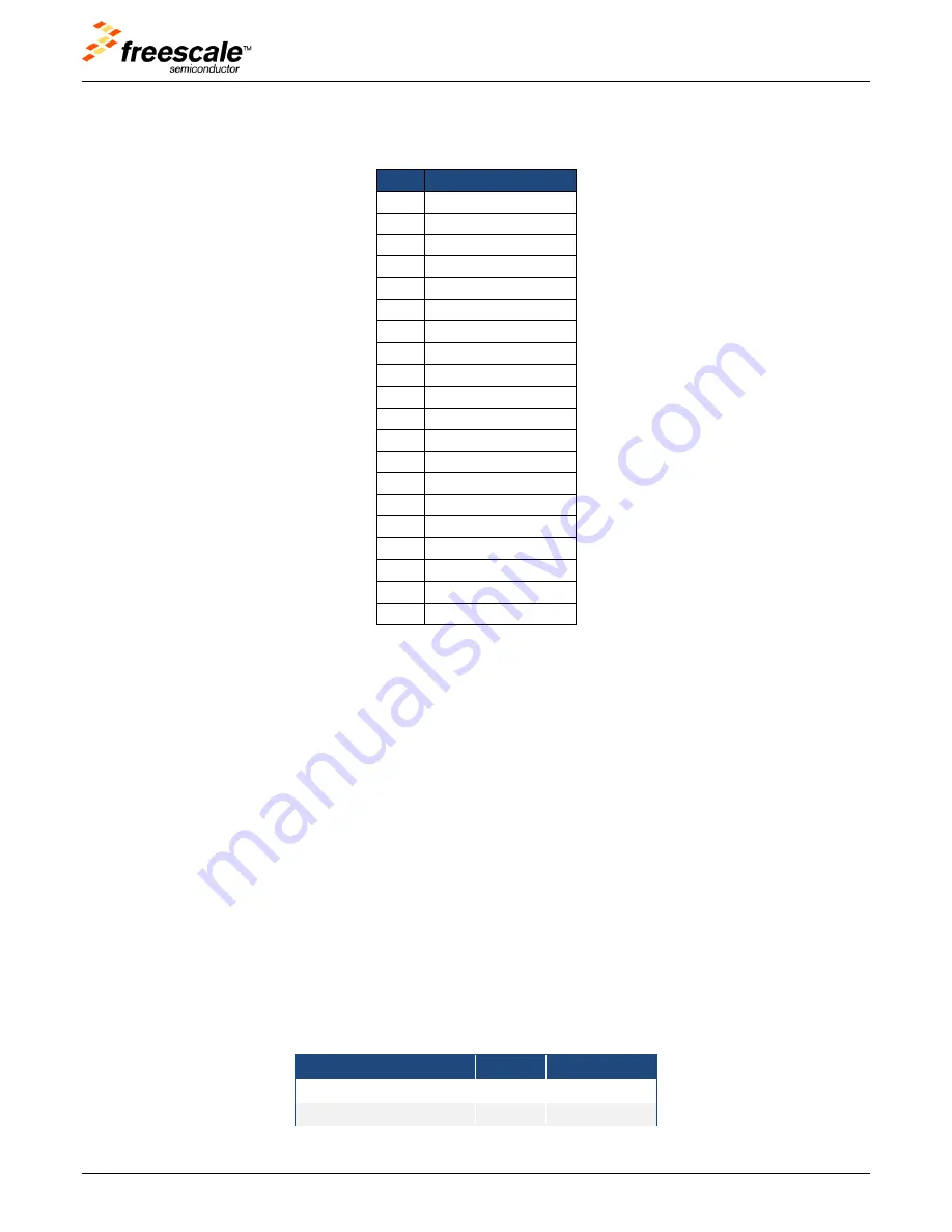
Table 3.
Touch TWRPI socket pinout
Pin
Description
1
5V VCC
2
3.3 V VCC
3
Electrode 0
4
3.3V VDDA
5
Electrode 1
6
VSS (Analog GND)
7
Electrode 2
8
Electrode 3
9
Electrode 4
10
Electrode 5
11
Electrode 6
12
Electrode 7
13
Electrode 8
14
Electrode 9
15
Electrode 10
16
Electrode 11
17
ADC: TWRPI ID 0
18
ADC: TWRPI ID 1
19
GND
20
Reset
2.13
Ethernet
The K70FN1M0 features a 10/100 Mbps Ethernet MAC with MII and RMII interfaces. The TWR-
K70F120M routes the RMII interface signals from the K70 MCU to the Primary Connector, allowing the
connection to an external Ethernet PHY device on a Tower peripheral module.
When the K70 Ethernet MAC is operating in RMII mode, synchronization of the MCU clock and the 50
MHz RMII transfer clock is important. The MCU input clock must be kept in phase with the 50 MHz
clock supplied to the external PHY. Therefore, the TWR-K70F120M provides the option (see jumper
descriptions Table 5) to clock the MCU from an external clock from the CLKIN0 pin on the Primary
Connector. The Tower peripheral module implementing the RMII PHY device should drive a 50 MHz
clock on the CLKIN0 pin that is kept in phase with the clock supplied to the RMII PHY.
The TWR-SER module that comes as part of the TWR-K70F120M-KIT provides a 10/100 Ethernet PHY
that can operate in either MII or RMII mode. By default the PHY is boot strapped to operate in MII
mode; therefore jumper configuration changes may be required. Table 4 shows the settings for proper
interoperability between the Ethernet interface on the TWR-SER and the TWR-K70F120M.
Table 4.
Ethernet operation jumper settings
Tower Module
Jumper
Setting
TWR-K70F120M(rev B)
J19
OFF
TWR-K70F120M(rev C)
J18
ON


