


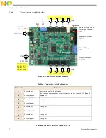

Configuration and Connections
Symphony SoundBite Reference Manual, Rev. 2.0
Freescale Semiconductor
9
3.7
Status LEDs: LED10–13
Four LEDs display the status of the board: D10–D12, D13.
3.8
Expansion Header: CON1
An expansion header (CON1) is provided to enable off-board expansion. The 5V and 3.3V power supplies
and several grounds are present on the CON1 header, as well as all GPSWx and GPLEDx lines.
Although the GPSWx lines are normally GPIO inputs, the GPSWx lines can be used as either inputs or
outputs at the CON1 header.
NOTE
When the GPSWx lines are used as an output, if the corresponding switch
position of SW1 is ON, the pull-up resistor is enabled, presenting an
additional load to the DSP GPIO pin when in the logic low state, which must
be accounted for.
Although the GPLEDx lines are normally GPIO outputs, the GPLEDx lines can be used as either inputs
or outputs at the CON1 header.
NOTE
When the GPLEDx lines are used as inputs, the external signal must be able
to handle the load that the presence of the LED and current limiting resistor
present to it. There are no provisions for disconnecting the LEDs from the
GPLEDx lines.
Additionally, you can modify the Symphony SoundBite board by soldering jumpers between the 4 solder
pads at CON1 to any of the 4 IRQ lines, IRQD:A, the I
2
C lines SDA and SCL, and GPIO pin PC7, as
desired.
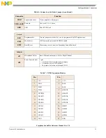
Table 5. Status LEDs
LED
Color
Description
D10
Amber
JTAG/OnCE
D10–D12 display the communication
protocol in use by the host PC.
D11
Amber
SDI/SPI
D12
Amber
SDI/I2C
D13
Green
Power Indicator
D13 indicates when power is applied to the
DSP and Analog Conversion functional
blocks of the Symphony SoundBite.


