


Configuration and Connections
Symphony SoundBite Reference Manual, Rev. 2.0
Freescale Semiconductor
11
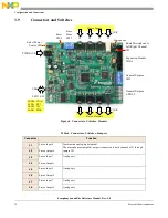
CON1
Expansion header
Do not populate with jumpers.
PWR_JACK
Power In
Coax jack, 2.1 x 5.5 mm
USB
USB
Mini-B USB jack
Switch
SW1
Programmable
General purpose switches (8x), can be programmed by DSP applications.
SW2
Mode Select
DSP boot mode select and EEPROM enable
SW3
Board Reset
Momentary switch, resets the Symphony SoundBite board.
Jumper
JP1
Microphone Select
Route Microphone output to Left or Right Channel
JP3
Power Source Select
3 pins.
• 1–2 jumper: Select external power supply.
• 2–3 jumper: Select USB (default).
• No jumpers: Select power through CON1.
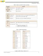
Table 7. CON1 Expansion Header
Pin
Pin
1
+5V
2
+3.3V
3
GND
4
PAD1
5
PAD2
6
PAD3
7
PAD4
8
GPLED8
9
GPLED0
10
GPLED7
11
GPLED1
12
GPLED6
13
GPLED2
14
GPLED5
15
GPLED3
16
GPLED4
17
GPSW0
18
GPSW7
19
GPSW1
20
GPSW6
21
GPSW2
22
GPSW5
23
GPSW3
24
GPSW4
25
GND
26
GND
Table 6. Connectors, Switches, Jumpers (continued)
Connector
Function


