

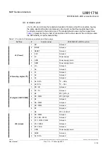


NXP Semiconductors
UM11714
PCF85263ATL-ARD evaluation board
Once installation is complete, assure that one of the mentioned three EVK with attached
PCF85263ATL-ARD daughterboard is connected to PC and powered-on. Open
NXP_GUI(PCF85063TP,PCF85263ATL,PCF85063A) GUI application. An interface will
.
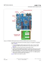
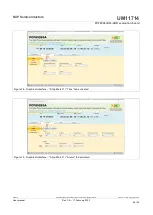
The GUI application starts with
Settings
tab (marked with red arrow). The left side of the
window displays
Board settings
. The section provides the following settings:
• Select EVK:
displays the list of EVKs. Selecting a wrong EVK board causes the
connection to fail and a pop-up window with the message:
“Unable to Connect with
EVK”
appears on the screen.
• Select COM port:
displays the port selected for communication. The port is
automatically selected by the system (in the picture is COM 3).
• Select Board:
allows the user to select the correct daughterboard (the application
can support three different boards). In
, the selected board is PCF85263A.
Selecting a wrong daughterboard causes the connection to fail and a pop-up window
with the message:
“Unable to Connect with Daughter Card”
appears on the screen.
In the right side of the window is located
Device Setting
section. From this section, two
settings are available:
I2C Frequency
, which sets the I
2
C-bus clock to 100kHz, 400kHz
or 1MHz.
• I2C Frequency:
selects the I
2
C-bus clock to 100kHz, 400kHz or 1MHz.
• RTC Mode:
selects between the RTC (
Real Time Clock
) or time elapsed (
Stop
Watch
) working mode. Selecting one of two modes for the DUT, involves changes in
the GUI. The second main tab name (from left to right) will reflect the selected RTC
Mode in
Device Setting
section.
Assuming the correct parameters are chosen, clicking the
Connect
button establishes
the connection with the EVK. In the bottom side of the GUI window a status bar shows in
real time the status regarding connection between PC and the EVK.
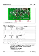
Figure 9. Graphical interface at start-up (“Settings” tab activated by default)
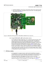
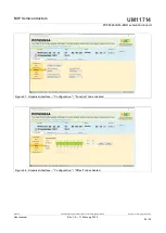
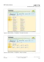
If from
Device Setting
section the
Real Time Clock
mode is selected, the second
main tab name is
Real Time Clock
. Clicking on
Real Time Clock
tab, a new window
appears (see
). From this section the user can control the internal registers of
UM11714
All information provided in this document is subject to legal disclaimers.
© NXP B.V. 2022. All rights reserved.
User manual
Rev. 1.0 — 17 February 2022
18 / 34