


NXP Semiconductors
UM11714
PCF85263ATL-ARD evaluation board
It is recommended to attach the PCF85263ATL-ARD to the Arduino connectors of the
IMX8MMINI-IARD interposer board first, and then the resulting assembly to the i.MX 8M
Mini LPDDR4 EVK. This can be done by plugging J1 connector located on the interposer
board to J1003 connector on the EVK.
To power-up the EVK, an USB-C type cable connected to PORT 2 of the EVK is used.
The power switch SW101 on the EVK board must be set to ON position to power-up
the setup. Data communication is achieved by routing a separate USB (Micro-B type)
cable from an USB port on the PC to debug port (J901) on the EVK (see
and
The user may find details regarding power-up and operation of the setup assembly in
8MMINILPDDR4-EVK user manual and IMX8MMINI-IARD User Manual. The files can be
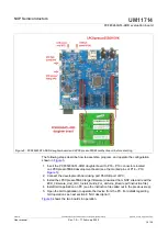
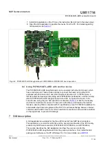
Figure 7. The assembly PCF85263ATL-ARD daughterboard, IMX8MMINI-IARD interposer board, and i.MX 8M Mini
LPDDR4 EVK, before starting
To configure and operate the setup, follow the below steps:
1. Insert the PCF85263ATL-ARD onto the IMX8MMINI-IARD interposer board Arduino
connectors (located on the top side);
2. Attach IMXMMINI-IARD connector plug J1 (located on the bottom of the board) into
J1003 expansion board located on the top side of i.MX 8M Mini LPDDR4 EVK (see
3. Power-up the EVK board using an USB Type C cable attached to PORT 2;
4. Connect the EVK to the PC, using an USB Micro-B cable, attached to J901 debug
port;
5. Place SW101 in ON position to power-up the boards;
6. Install the MIMXRT1050 target firmware (download
and firmware installation manual
UM11714
All information provided in this document is subject to legal disclaimers.
© NXP B.V. 2022. All rights reserved.
User manual
Rev. 1.0 — 17 February 2022
16 / 34