


NXP Semiconductors
UM11711
PCAL6524EV-ARD evaluation board
•
i.MX 8M Mini LPDDR4 EVK Board;
Each mentioned above evaluation / development board benefits by firmware support
which can be downloaded from NXP company site (
the EVK motherboard must be programmed with the corresponding firmware package.
Additionally, a GUI application (Windows 10) is available for download from the NXP
site, allowing rapid testing and operation of PCAL6524EV-ARD daughterboard through
the one of above mentioned EVK. The GUI application is common for all three EVKs
and for the PCAL6xxx I/O expander development card family, manufactured by NXP
(PCAL6408A, PCAL6416A, PCAL6524 and PCAL6534 ICs). For details regarding
installation of the EVK firmware and GUI host software on PC please download
EVK_Firmware_And_GUI_Install_Guide_For_Arduino_Boards.pdf instruction file from
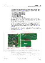
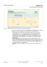
). Once the software is installed, the first step is to select the
correct combination EVK – PCAL6524EV-ARD daughter card, and then the board can be
controlled from the GUI interface. See
and
for more details regarding
the operation of PCAL6524EV-ARD from GUI software.
6 Configuring the hardware
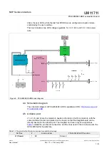
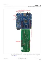
6.1 Using the PCAL6524EV-ARD with an IMXRT1050 EVK board
shows the required hardware for operation of the PCAL6524EV-ARD
daughterboard with IMXRT1050 EVK. The following items are necessary:
•
One IMXRT1050-EVK board
•
One PCAL6524EV-ARD daughterboard
•
One USB-A / USB Micro-B cable
•
A PC with Windows 10 operating system
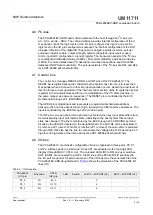
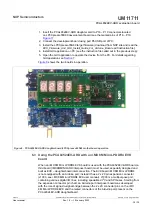
The IMXRT1050 EVK motherboard can be powered by one of the three methods:
•
Connecting an external 5VDC power supply to the barrel power connector (J2) on the
board
•
Connecting a USB cable from the PC to the Micro-B USB connector (J9) on the board
•
Connecting a USB cable from the PC to the USB connector (J28) on the board. When
the PC is connected in this fashion, the USB port can simultaneously act as a debug
interface. Therefore, by using a single USB cable connected to J28, the EVK can be
powered and at the same time linked to the PC for data exchange.
The older USB ports (from PC) are not able to deliver the necessary current (500mA),
before establishing the communication, use an external power supply (connected to J2).
From J1 on the EVK board (see
) the user can select the power configuration for
the motherboard. For further details, refer to the IMXRT1050 EVK Board Hardware User
Guide.
UM11711
All information provided in this document is subject to legal disclaimers.
© NXP B.V. 2022. All rights reserved.
User manual
Rev. 1.0 — 19 January 2022
15 / 30