


Specifications
MIMXRT1064 EVK Board Hardware User’s Guide, User's Guide, Rev. 0, 10/2018
12
NXP Semiconductors
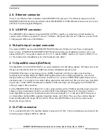
D6/AIN0/PWM/OC0A
D7/AIN1/PWM
J24
J25
D8/CLKO/ICP1
NC
D9/OC1A/PWM
IOREF
D10/SPI_CS
RESET
D11/OC2A/PWM/SPI_MOSI 3.3V
D12/SPI_MISO
5V
D13/SPI_CLK
GND
GND
GND
AREF
VIN
D14/I2C_SDA
D15/I2C_SCL
2.14. Camera module connector
One parallel CSI (Camera Sensor Interface) is supported by the i.MX RT1064. There is a Camera
Module Connector (J35) on the MIMXRT1064 EVK Board. The CA031C based on OV7725 and
CA111C based on MT9M114 can be used directly.
NOTE
J35 supports both MT9M114 and OV7725 camera module, but 3.3 V is a
violation to MT9M114 spec 3.1 V. It proved fine for evaluation/demo
with 3.3 V supply, but in product design, it is recommended to adjust
DCDC output or add level shifter.
2.15. User interface switch
There are four user interface switches on the MIMXRT1064 EVK Board. Their functionality is as
below.