


Specifications
MIMXRT1050 EVK Board Hardware User’s Guide, User's Guide, Rev. 2, 03/2018
8
NXP Semiconductors
J28
5-6
NOTE
For some computers’ USB, it cannot support 500ma before establishing
communication. In this case, it is recommended to replace the computer or
use the power adapter(J2) to power the EVK Board.
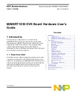
The power tree is shown in the following figure.
Figure 4. Power Tree
The power control logic of the MIMXRT1050 EVK board is shown in the following figure:
For A0 silicon:
•
It will power up SNVS and DCDC_IN together firstly, then PMIC_REQ_ON will be switched
on to enable external DC/DC to power up other power domains.
•
ON/OFF button is used to switch ON/OFF PMIC_REQ_ON to control power modes.
•
RESET button and WDOG output are used to reset the system power.
For A1 silicon:
•
It will power up SNVS firstly, then PMIC_REQ_ON will be switched on to enable external
DC/DC to power up other power domains.
•
ON/OFF button is used to switch ON/OFF PMIC_REQ_ON to control power modes.
•
RESET button and WDOG output are used to reset the system power.