TIXU_MX6Y
Rev. A1_02
6
3
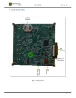
BOTTOM VIEW
Figure 3: Bottom View
Страница 1: ...lation Guide Rev A1_02 19 05 2020 TIXU_MX6Y i MX 6ULL PROCESSOR POWER DESIGN WITH TI PMIC Revision History Date Rev No Description By 02 04 2020 A1_01 Initial Draft VVDN 19 05 2020 A1_02 Images update...
Страница 2: ...ECTING THE FPC CABLE 8 4 4 CHANGING THE BOOT OPTION 9 4 4 1 Boot option for SW6 9 4 4 2 Boot option for SW7 9 4 5 INSERTING THE USD CARD 11 4 6 INSERTING THE COIN CELL 12 4 7 CONNECTING DEBUG UART 12...
Страница 3: ...7 Connecting FPC cable 9 Figure 8 SD Boot configuration 10 Figure 9 eMMC boot configuration 11 Figure 10 Connecting uSD card 11 Figure 11 Inserting coin cell 12 Figure 12 Connecting Debug UART cable...
Страница 4: ...ION This document contains information about the power up and user interfaces of the i MX 6ULL EVAL board powered by Texas instruments TPS6521815 2 TOP VIEW Figure 1 Top view Note More information on...
Страница 5: ...TIXU_MX6Y Rev A1_02 5 2 1 Top view without LCD Figure 2 Top view without LCD...
Страница 6: ...TIXU_MX6Y Rev A1_02 6 3 BOTTOM VIEW Figure 3 Bottom View...
Страница 7: ...the FPC cable to the receptacle J9 and lock the cable 4 Fix the M2 screws 5 Configure the required boot option using DIP switches 6 Insert the coin cell to the battery holder 7 Connect the SD card 8 C...
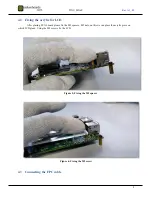
Страница 8: ...for LCD After placing EVAL board please fix the M2 spacers M2 nuts on this we can place the acrylic piece on which LCD glued Using the M2 screws fix the LCD Figure 5 Fixing the M2 spacer Figure 6 Fixi...
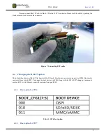
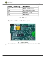
Страница 9: ...FPC cable 4 4 Changing the BOOT option The default boot device of the EVAL board will be SD card Boot device can select using switch SW6 Boot mode can select from switch SW7 To change the boot device...
Страница 10: ...e 2 SW7 Boot option Please make sure to set the boot options to SD as shown in below figure Figure 8 SD Boot configuration User can refer below figure to configure eMMC card boot option Resistor chang...
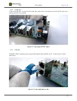
Страница 11: ...figuration 4 5 Inserting the uSD card User can flash the uSD card with boot image and that can insert to the Connector J2 It is a push in Push out uSD connector Please refer the below figure for conne...
Страница 12: ...g of all functionality Please refer below figure to insert the coin cell Figure 11 Inserting coin cell 4 7 Connecting Debug UART For getting console access a USB micro B cable needed Micro B end need...
Страница 13: ...vice or usb cable USB cable can connect to the board as shown below Figure 13 Connecting USB cable 4 9 Connecting the User Interface Devices Optional Below are the User Interfaces which can connect to...
Страница 14: ...own below Please make sure the Key of the connector is aligning with silk screen marking Figure 14 Connecting USB2ANY header 4 9 2 Ethernet 100BASE T Ethernet communication is supported through the du...
Страница 15: ...ug of the adapter to the jack please use switch SW1 to turn on the power Figure 16 Connecting adapter 4 11 On board LED Information Below is the information about all LED used in the board The marking...
Страница 16: ...DCDC6 of PMIC Whether it is coincell or not Orange means it powerd from coincell Blue means powered from main supply 9 This will let know the user whether any reception of data happened in console 10...