NXP Semiconductors i.MX 6SLL Скачать руководство пользователя страница 9

 www.nxp.com 

  Quick Start Guide 

9

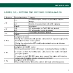
JUMPER, PUSH BUTTONS AND SWITCHES CONFIGURATION

Reference

Shunt Installation Function

J16

1–2

Use cable to pins 1 and 2 to connect an external 

charger

2–3

Shunt 2–3 to experiment with USB charging

OpenD

No charger

J17

1–2

5 V rail supplied by PMIC (600 mA limited)

2–3

5 V rail supplied from wall adapter

J14

1–2

Connect the coin cell if needed

OpenD

SW14

Evaluation kit switch 

•  Sliding the switch to the ON position connects the 5 V power supply to the 

Evaluation Kit main power system.

•  Sliding the switch to the OFF postition immediately removes all power 

from the board.

SW1

Evaluation kit ON/OFF button 

•  Prolonged depress (>5 sec) will force an immediate hardware shutdown.
•  If board is in the SHUTDOWN state, short press of the button will restart 

(boot) the system.

•  If board is in the STANDBY state, short press of the button will bring the 

system out of standby (resume operations, no boot).

SW2

Evaluation kit RESET button 

•  Press of the button will reset the system and begin a boot sequence.

Содержание i.MX 6SLL

Страница 1: ...Quick Start Guide i MX 6SLL Evaluation Kit...

Страница 2: ...tex A9 core 2 GB LPDDR3 400 MHz eMMC unpopulated SD socket for boot code SD socket for Wi Fi and external device Audio codec LCD expansion port connector EPDC expansion port unpopulated Board mounted...

Страница 3: ...X 6SLL EVK includes the following items Board MCIMX6SLL EVK Cables USB AM TO MICRO USB 5P 1 0M Power supply 100 240 V input 5 V 4 A output Documentation Quick Start Guide this document SD cards contai...

Страница 4: ...W THE i MX 6SLL EVK Quick Start Guide 4 Power Switch Debug USB USB Host USB OTG SD1 SD3 Booth Device Switches 5V Power Jack Boot Mode Switch PMIC Audio Jack SPK Out EMMC Figure 1 Front side of i MX 6S...

Страница 5: ...5 www nxp com JTAG i MX 6SLL applications processor Bluetooth LCD MIC ON OFF RESET LPDDR3 Figure 2 Back side of i MX 6SLL EVK bottom...

Страница 6: ...Once the PC recognizes the virtual USB to UART device it can be seen it in your PC Device Manager list Serial port configuration 115 2 Kbaud 8 data bits 1 stop bit no parity Note The PC needs a drive...

Страница 7: ...on the EVK board During the boot process there will be operating system status information scrolling on the terminal window of the PC if connected The Linux penguin images will initially appear in th...

Страница 8: ...the switch configuration of boot device for i MX 6SLL EVK SD1 is chosen as default BOOT_MODE 1 0 BOOT TYPE 00 Boot from fuses 01 Serial downloader 10 Internat boot 11 Reserved Table 1 Boot options BOO...

Страница 9: ...the switch to the ON position connects the 5 V power supply to the Evaluation Kit main power system Sliding the switch to the OFF postition immediately removes all power from the board SW1 Evaluation...

Страница 10: ...power supply from the system by opening transistor Q1 in case the supply voltage exceeds 5 5 V The user must take into account this is the maximum voltage that can be plugged into J6 MCIMX6SLL EVK sch...

Страница 11: ...www nxp com 11...

Страница 12: ...LLEVK NXP and the NXP logo are trademarks of NXP B V All other product or service names are the property of their respective owners All rights reserved 2014 2017 NXP B V Document Number IMX6SLLEVKQSG...

Отзывы: