


Distributor of NXP Semiconductors: Excellent Integrated System Limited
Datasheet of MCIMX53SMD - TABLET SABRE PLATFORM MCIMX53
Contact us: [email protected] Website: www.integrated-circuit.com
Freescale Semiconductor
MCIMX53SMD Board Hardware User’s Guide, Rev. 0
19
4.
MCIMX53SMD Board Connectors
The MCIMX53SMD board provides a number of connectors for a variety of inputs and outputs to and from the
board. The following subsections describe these connections in detail.
4.1.
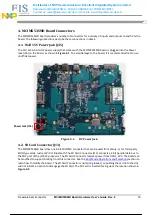
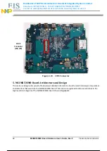
Wall 15V Power Jack (J35)
The 15V at 3A AC-to-DC power supply that comes with the MCIMX53SMD board is plugged into the Power
Jack (J35) on the board, as shown in
Figure 4-1
. To avoid damage to the board, it is recommended not to use
unofficial power.
Figure 4-1.
DC Power Jack
4.2.
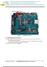
SD Card Connector (J13)
The MCIMX53SMD board has one 4-bit SD/MMC connector that can be used for memory, or for third-party
SDIO type cards, such as WiFi or Bluetooth. The SD Card Connector (J13) connects a 4-bit parallel data bus to
the SD1 port of the i.MX53 processor. The SD Card Connector receives power from DCDC_3V3. The board can
be modified to support booting from this connector. See the
Boot Mode Operations and Selections
section to
learn how to modify the board. The SD Card Connector is not spring loaded, so pushing the card into the slot
will not initiate an action to disengage the SD Card. The SD Card is inserted facing up at the location shown in
Figure 4-2
.
Power Jack (J35)
20 / 82
20 / 82