NXP Semiconductors Freescale KIT33905 Скачать руководство пользователя страница 12

KIT33905 Evaluation Boards

, Rev. 2.0

12

Freescale Semiconductor

Using the EVB

7.1.1

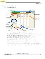
Sending Commands to Read Flags Set on SBC

Device Status and
Flags sections

Flags decoded

Read device’s Flags
and status

Read Device  Mode – keeps 
SAFE functionality and exits
DEBUG Mode (overrides 
hardware configuration)

Adds command 
to 

Sequential Mode

sequence 

Adds all commands on 
tab to 

Sequential Mode

sequence 


Figure 5. SPIGen Graphical User Interface (Commands and Flags Decoded)

1. In the 

Registers and Flags

 tab, click 

Flag High and Low

 sub tab to read the device status and clear 

flags as shown in 

Figure 5

.

2. Click any of the read device flag status


options.

3. Click 

SEQ

 to add commands to the Sequential Mode window.

Содержание Freescale KIT33905

Страница 1: ...KEVBE 5 Volt KIT33905BD3EVBE 3 3 Volt Figure 1 KIT33905D5EKEVBE KIT33905BD3EVBE Evaluation Boards Table of Contents 1 Kit Contents Packing List 2 2 Important Notice 3 3 Introduction 4 4 Required Equip...

Страница 2: ...ards Rev 2 0 2 Freescale Semiconductor Kit Contents Packing List 1 Kit Contents Packing List KIT33905D5EKEVBE or KIT33905BD3EVBE Hardware CD33905 includes SPIGen Software CABLE RIBBON FLAT 16 PIN ASSY...

Страница 3: ...the date of delivery and will be replaced by a new kit Freescale reserves the right to make changes without further notice to any products herein Freescale makes no warranty representation or guarant...

Страница 4: ...graphical user interface paired up with the SPI dongle board KITUSBSPIDGLEVME through the 2x8 pin ribbon cable Additionally for added flexibility the user can implement a custom board with a microcon...

Страница 5: ...des CAN or LIN bus I O transition automatic timer SPI message and VDD over current detection Voltage current and temperature protection with enhanced diagnostics that can be monitored by the system vi...

Страница 6: ...KIT33905 Evaluation Boards Rev 2 0 6 Freescale Semiconductor EVB Setup Configuration 5 EVB Setup Configuration Figure 2 EVB Setup Configuration Diagram...

Страница 7: ...Standard EVB configuration set up the jumpers as shown on Figure 3 If the jumper configuration is in accordance with Jumper Connections on page 8 The VDD D3 and the 5V_CAN D4 LEDs must be ON at startu...

Страница 8: ...implemented J23 I O0 configuration 1 2 closed 4 7 kohm pull down resistor to GND and indicator LED implemented 2 3 closed 15 kohm pull up resistor to VSUP and indicator LED implemented J24 I O1 config...

Страница 9: ...with VDD ON a transition on CS is a wake up condition 5 TXDC_I CAN bus transmit data input Internal pull up to VDD 6 RXDC CAN bus receive data output 7 I_WAKE_I Active high input to enable on board F...

Страница 10: ...in function is to reset the MCU It has an internal pull up to VDD The reset input voltage is also monitored in order to detect external reset and safe conditions 6 MOSI SPI data received by the device...

Страница 11: ...rents are sufficient to supply the device 4 To use SPIGen go to the Windows Start menu Programs SPIGen and click on the SPIGen icon The SPIGen Generic SPI Generator GUI will appear 5 Go to the Configu...

Страница 12: ...exits DEBUG Mode overrides hardware configuration Adds command to Sequential Mode sequence Adds all commands on tab to Sequential Mode sequence Figure 5 SPIGen Graphical User Interface Commands and Fl...

Страница 13: ...of corresponding tab address bits 15 8 not shown Device Selection Function to be written of corresponding tab Send command as configured to corresponding tab address Read device status and enabled fun...

Страница 14: ...on tab to Sequential Mode sequence Read device status and enabled functionality Read Device Mode keeps SAFE functionality and exits DEBUG Mode overrides hardware configuration Figure 7 SPIGen Graphica...

Страница 15: ...ds sent and received from the SBC s MOSI and MISO pins Figure 8 SPIGen Graphical User Interface Sequential Mode 1 Click Sequential Mode tab This window displays all commands in the Sequential Mode seq...

Страница 16: ...of device s features Mouse over for Information Automated state diagram Mouse over for information Figure 9 SPIGen Graphical User Interface Automated State Diagram Mode 1 Click Diagram tab 2 Select No...

Страница 17: ...NC_4 20 NC_5 21 NC_6 22 NC_7 27 NC_8 28 NC_9 29 NC_10 30 NC_11 32 NC_12 33 NC_13 34 NC_14 35 NC_15 52 NC_16 53 NC_17 54 J21 HDR 1X2 J21 HDR 1X2 1 2 R20 4 7K R20 4 7K D1 MBRS140 D1 MBRS140 2 1 D13 1N41...

Страница 18: ...KIT33905 Evaluation Boards Rev 2 0 18 Freescale Semiconductor Board Layout 9 Board Layout 9 1 Assembly Drawing Figure 11 Assembly Drawing 9 2 Top Side Layer Figure 12 Top Side Layer...

Страница 19: ...KIT33905 Evaluation Boards Rev 2 0 Freescale Semiconductor 19 Board Layout 9 3 Bottom Side Layer Figure 13 The Bottom Side Layer...

Страница 20: ...TSW 108 07 G D 15 1 J13 DIP14 SKT DIP 14 PINS TH 3M ICE 143 S TG30 16 5 J15 J21 J22 J27 J28 HDR 1X2 HDR 1X2 TH 100MIL SP 330H SN SAMTEC TSW 102 07 T S 17 2 J23 J24 HDR_1X3 HDR 1X3 TH 100MIL SP 330H AU...

Страница 21: ...om files analog doc fact_sheet MC33903_4_5FS pdf Application Note www freescale com files analog doc app_note AN3865 pdf Errata http www freescale com files analog doc errata MC33903_4_5ER pdf SPIGen...

Страница 22: ...in this document Freescale Semiconductor reserves the right to make changes without further notice to any products herein Freescale Semiconductor makes no warranty representation or guarantee regardi...

Отзывы: