


Freescale Freedom Development Board FRDM-CR20A User’s Guide, Rev. 0, 04/2015
Freescale Semiconductor, Inc.
7
FRDM-CR20A development board
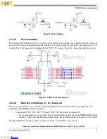
Figure 3
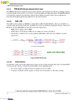
also shows a footprint of the FRDM-CR20A with the location of the IO headers. The following
list gives these details:
•
J1, J2, J3 and J4:
— Headers have standard 0.1 in / 2.54 mm pin spacing
— J2 is 10-pin
— J1 and J3 are 8-pin
— J4 is 6-pin
— Pin headers mounted on the top side of the FRDM-CR20A board and are intended to plug into
matching receptacles on the Freescale Freedom platform board.
•
J6:
— Header has standard 0.1 in / 2.54 mm pin spacing
— J6 is a 1x2 pin, with a cut-trace on bottom side
— Pin headers mounted on the top side of the FRDM-CR20A and is intended to isolate for a IC
current measurements.
•
J7:
— Header has standard 0.1 in / 2.54 mm pin spacing
— J7 is 1x3 pin
— Pin headers mounted on the top side of the FRDM-CR20A board and intended to select the
Reset target main MCU or transceiver.
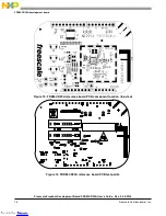
Figure 4. FRDM-CR20A top side (component side) footprint
Downloaded from
Downloaded from
Downloaded from
Downloaded from
Downloaded from
Downloaded from
Downloaded from