


Freescale Freedom Development Board FRDM-CR20A User’s Guide, Rev. 0, 04/2015
Freescale Semiconductor, Inc.
11
FRDM-CR20A development board
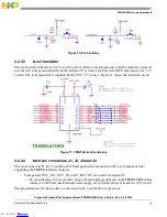
Figure 7. FRDM-CR20A 32 MHz reference oscillator circuit
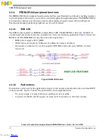
4.2.3
Power management
The FRDM-CR20A development board must be powered through the edge connectors from the Freescale
Freedom development platform board that it is plugged into. The FRDM-CR20A power management
circuit is shown in
Figure 8
.
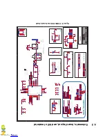
Figure 8. FRDM-CR20A power management circuit
The two-pin header J6 provides the means to supply current to various board components and current
measurements if desired. The red LED marked as LED1 is available as a power indicator. The power
header/0 ohm resistor provides the means to supply either the IC or board circuits. Current measurements
can be made by inserting a current meter in place of a designated jumper. Connections configurations are
described in
Table 2
.
Table 2. Power distribution headers
Supply Designation
Header Pins
Description
P3V3_BRD
R4
1 - 2
Supply voltage to LEDs
• Normally jumpered
• Jumper used to enable LEDs, SW’s and Level Translator on board
• Leave open for lowest power
• Usage: Measure board current
P3V3_IC
J6
1 - 2
Supply voltage to MCR20A
• Normally jumpered
• Supplies the MCR20A tranceiver
• Usage: Measure or supply radio current
Downloaded from
Downloaded from
Downloaded from
Downloaded from
Downloaded from
Downloaded from
Downloaded from
Downloaded from
Downloaded from
Downloaded from
Downloaded from