


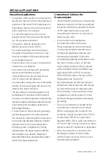


The twin Ericore conductors are run in a
parallel manner down to the base before
they split to the oposite side of the structure
(see Figure
27
). The usual conductive saddle
spacing applies.
Figure
27
: Exploded view of the Dual Coupling Termination
A typical mast arrangement is shown in
Figure
27
. Two mast assemblies comprised
of an aluminum lower mast section, an
inline coupler, and upper FRP mast must
be independently supported. Each upper
termination must be connected to the Dual
Coupler assembly (TERMDUALCOUP) and
secured by the provided couplers (Ericore/
UTSP) and bolts provided. The spacing of
the two mast assemblies is
140
mm (
5
.
5
in.)
which is determined by the dimensions
of the dual coupler assembly. The nVent
ERICO Dynasphere (D/SMKIV-SS) shall be
installed in the center hole with the butt
adapter and tightened with the provided
bolt. Each Ericore cable shall exit their
respective inline couplers and be affixed
to the mast assembly by stainless steel
straps at the normal interval of at least
every
1
m (
40
in).
At the point of connection to the grounding
system, each nVent ERICO Ericore cable
is fitted with an nVent ERICO Ericore
lower termination kit, and attached to the
grounding system.
Dynasphere nVent ERICO PN D/SMKIV-SS (
702085
)
Mast Butt Adapter nVent ERICO PN Intcptadbutt
(
702296
)
Dual E
2
Coupling System Main Plate nVent
ERICO PN Terumualcoup
Bonding Termination for Ericore Cable nVent
ERICO PN Ericore/UTSP
Mast Butt Adapter nVent ERICO PN Intcptadbutt
(
702296
)
Ericore Upper Termination nVent ERICO PN
Ericore/TRM/OS (
701915
)
FRP Mast nVent ERICO PN FRP
2
MBLACK
(
702040
)
Inline Coupler nVent ERICO PNI/LCOUPL (
701320
)
Ericore Cable nVent ERICO PN Ericore (
701875
)
SS Mounting Bracket nVent ERICO PN
7000250
S
4
(
702065
)
Conductive Saddle nVent ERICO PN CONDSADFX
(
702065
)
Aluminum Mast
Ericore Dual Connection
Cantilevered Masts