background image

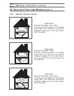
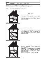
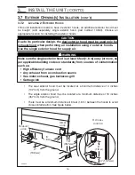
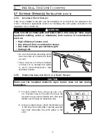
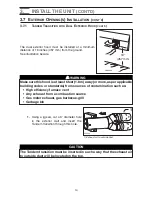
The dual exterior hood must be installed at a minimum 
distance of 18 inches (457 mm) from the ground.
See illustration beside.

1.

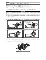
Using a jig saw, cut a 6’’ diameter hole
in the exterior wall and insert the 
Tandem transition through this hole. 

3.

INSTALL THE  UNIT 

(CONT’D)

3.7 E

XTERIOR

O

PENING

(

S

) I

NSTALLATION

(

CONT

D

)

3.7.1

T

ANDEM

T

RANSITION WITH

D

UAL

E

XTERIOR

H

OOD

(

CONT

D

)

VD00

8

3A

1

8

(457 mm)

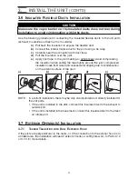
WARNING

Make sure this hood is at least 6 feet (1.8 m) away (or more, as per applicable
building codes or standards) from sources of contamination such as:

• High efficiency furnace vent
• Any exhaust from a combustion source
• Gas meter exhaust, gas barbecue-grill
• Garbage bin

!

VD0084

1

CAUTION

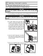
The Tandem transition must be inserted in such a way that the exhaust air
to outside duct will be located on the top.

1

3

1) Exhaust air to outside duct

Содержание EA1500

Страница 1: ...anual Address of your installer 06095 rev A AE60 EA 1500 HV 1 5 VB0063 RESIDENTIAL USE ONLY INSTALLER LEAVE THIS MANUAL WITH THE HOMEOWNER HOMEOWNER USE AND CARE INFORMATION ON PAGES 20 TO 24 READ AND SAVE THESE INSTRUCTIONS ...

Страница 2: ...r heat producing appliance Do not connect the unit ducts to the furnace ducts neither return plenum or supply 12 When performing installation servicing or cleaning the unit it is recommended to wear safety glasses and gloves 13 When the federal provincial or state legislation comprises more restrictive installation and or certification requirements the aforementioned requirements prevail on those ...

Страница 3: ... starting the installation Please note the illustrations are typical ones We welcome any suggestions you may have concerning this manual and or the unit and we would appreciate hearing your comments on ways to better serve you Please forward all correspondence to us at the address indicated on the product registration card included with this manual This manual uses the following symbols to emphasi...

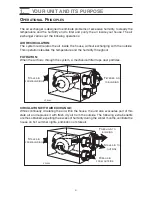
Страница 4: ... The air exchanger is designed to eliminate problems of excessive humidity to steady the temperature and the humidity and to filter and purify the air inside your house The air exchanger carries out the following operations AIR RECIRCULATION The system recirculates the air inside the house without exchanging with the outside This operation steadies the temperature and the humidity throughout FILTR...

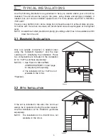
Страница 5: ...stallation kit no EA20130 purchase separately NOTE The installation kit no EA20130 is not available in the U S A 2 1 BASEMENT INSTALLATION VH0004 2 2 ATTIC INSTALLATION Use the following illustrations as guidelines to help you decide where your unit will be installed The unit should be hung to the joists using chains and springs included If needed this unit can be installed upside down For more de...

Страница 6: ...sing the installation kit no 15273 or no EA20130 not available in the U S A install these 5 diameter adapters Use 4 screws included per adapter to attach them to the unit See figure below The joists opening needed to install the Tandem transition must be 9 248 mm minimum Also the maximum heigh of the tandem transition is 8 222 mm See Tandem transition end view below NOTE The Tandem transition is i...

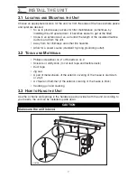
Страница 7: ...Allow for a power source standard 3 prong grounding outlet 3 1 LOCATING AND MOUNTING THE UNIT Phillips screwdriver no 2 or Robertson no 2 Scissors or utility knife to cut duct tape and flexible ducts Duct tape Jig saw A pair of metal shears if the exterior covering of the house is aluminum or vinyl A chisel and hammer if the exterior covering of the house is brick Caulking gun and caulking 3 2 TOO...

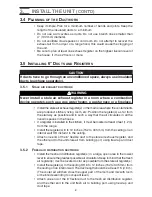
Страница 8: ...iling Attach one end of the 6 flexible duct to the stale air exhaust register and the other end to the unit stale air from building port using tie wrap and duct tape 3 5 INSTALLING 6 DUCTS AND REGISTERS WARNING Never install a stale air exhaust register in a room where a combustion device operates such as a gas water heater a gas furnace or a fireplace 3 5 1 STALE AIR EXHAUST DUCTWORK Install the ...

Страница 9: ...level of the house 1 2 A VA0033 BUNGALOW Basement stairwell A Closed One stale air exhaust register 1 in the highest lived in level of the house and one fresh air distribution register 2 in the lowest lived in level of the house For the closed stairwell use floor grilles A 1 2 A VA0034 BUNGALOW Basement stairwell A Open central Two stale air exhaust registers 1 in the highest lived in level of the...

Страница 10: ...house 1 1 2 A VA0036 COTTAGE Basement stairwell A Open Two stale air exhaust registers 1 in the upper lived in levels of the house and one fresh air distribution register 2 in the lowest lived in level of the house 1 1 2 A A VA0037 COTTAGE Basement stairwell A One part open some parts closed B One stale air exhaust register 1 in the highest lived in level of the house and one fresh air distributio...

Страница 11: ...on with duct tape d Pull the insulation over the joint e Apply duct tape to the joint making an airtight seal Avoid compressing the insulation when pulling the tape tightly around the joint compressed insulation loses its R value and causes water dripping due to condensation on the exterior surface of the duct a b c d e NOTE In a retrofit installation there maybe only one insulated duct already in...

Страница 12: ...ct tape gently to the joint in order to make an airtight seal See figures below VJ0025 VJ0022 VJ0023 VJ0024 1 2 3 4 EXHAUST AIR TO OUTSIDE DUCT ON TOP SECTION 12 3 7 1 TANDEM TRANSITION WITH DUAL EXTERIOR HOOD CONT D CAUTION Always connect the exhaust air to outside duct on top section of the Tandem transition Dual exterior hood requires assembly Using 2 no 8 x 3 4 screws assemble the top metal sc...
Страница 13: ... 3 7 1 TANDEM TRANSITION WITH DUAL EXTERIOR HOOD CONT D VD0083A 18 457 mm WARNING Make sure this hood is at least 6 feet 1 8 m away or more as per applicable building codes or standards from sources of contamination such as High efficiency furnace vent Any exhaust from a combustion source Gas meter exhaust gas barbecue grill Garbage bin VD0084 1 CAUTION The Tandem transition must be inserted in su...

Страница 14: ...line with caulking 3 INSTALL THE UNIT CONT D 3 7 EXTERIOR OPENING S INSTALLATION CONT D 3 7 1 TANDEM TRANSITION WITH DUAL EXTERIOR HOOD CONT D 2 Join the end of the Tandem transition to the rear of the exterior backplate Secure with 2 Xmas tree pins and seal properly with duct tape VD0085 CAUTION The exterior backplate must be installed with the word TOP pointing upward Xmas tree pin VD0086 VD0087...

Страница 15: ... from the ground There must be a minimum distance of 6 feet 1 8 m between the hoods to avoid cross contamination See figure below 15 CAUTION Due to its particular design the dual exterior hood must be used only for exhaust hood when performing an installation using 2 exterior hoods Use the single exterior hood for supply air VD0094 EXHAUST HOOD INTAKE HOOD 4 102 MM 6 1 8 M 6 1 8 M 18 457 MM 4 102 ...

Страница 16: ...lation over the joint Pull the vapor barrier over the insulation and over the outer ring of the exterior backplate Apply gently duct tape to the joint making an airtight seal B 3 Attach the exterior backplate to the exterior wall Using four provided screws fix it to the wall Seal the backplate with caulking as shown beside 4 Snap each assembled exterior hood on its respective backplate location an...

Страница 17: ...ation to expose the flexible duct Run each flexible duct through its respective hole 2 Using provided screws attach the flexible duct to the ring of the soffit grille Carefully seal with duct tape Assemble the soffit grilles to the soffit VD0160 6 1 8 M VI0014 WARNING Make sure the air intake grille is at least 6 feet 1 8 m away or more as per applicable building codes or standards from sources of...

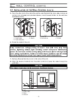
Страница 18: ...the backplate 2 3 Take one end of the cable and pass it through the wall control backplate or outlet box or mounting bracket 4 Splice back this end of the cable to access to the 4 wires Remove the insulated sleeve of each wire ends Make a loop with each bare end wire to hook them to their corresponding screw Connect YELLOW wire to Y screw RED wire to R screw GREEN to G screw and BLACK to B screw S...

Страница 19: ...over the cable control and pass the cable through the grommet 1 Cable control 2 Sleeve 3 Grommet 4 WALL CONTROL CONT D 4 1 INSTALLATION OF THE WALL CONTROL CONT D 19 VC0052 VC0051 1 2 3 4 5 2 3 4 1 CAUTION Keep control low voltage wiring at least 1 foot 305 mm away from motors lightning ballast light dimming circuit and power distribution panel Do not route control wiring along with house power wi...

Страница 20: ...IS ON NORMAL OR BOOST POSITION FILTER MAINTENANCE INDICATOR FLASHES EVERY SECOND TO INDICATE IT IS TIME TO PERFORM BIANNUAL MAINTENANCE SEE SECTION 5 LIGHTS UP WHEN ITS TIME TO PERFORM ANNUAL MAINTENANCE SEE SECTION 5 RECIRCULATION UNIT IS OPERATING ON NORMAL SPEED WITHOUT EXCHANGING AIR WITH THE OUTSIDE BOOST UNIT IS OPERATING ON HIGH SPEED RESET FILTER HOLE ONCE THE MAINTENANCE DONE RESET THE FI...

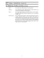
Страница 21: ...his position Generally used when extreme conditions occur e g parties smokers etc RECIRCULATION For a normal speed operation without exchanging air with the outside slide the button on this position This mode is recommended in high humidity days rain heat wave Also use it when the outside temperature is extremely cold and or the inside air is too dry It can be used also to recirculate the heat com...

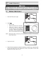
Страница 22: ...but the aluminum frame might tarnish 3 Plug back the unit 4 Reset the filter maintenance indicator by inserting a small rod e g paper clip end into the reset filter hole of the optional wall control Press lightly until the Filter Maintenance indicator light turns off 5 1 BIANNUAL MAINTENANCE 5 MAINTENANCE VD0005 WARNING Risk of electrical shocks Before performing any maintenance or servicing alway...

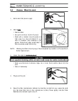
Страница 23: ...he top tray of the dishwasher is possible but the aluminum frame might tarnish 3 Check the exterior air intake hood Make sure there are no leaves twigs ice or snow that could be drawn into the vent Clean if necessary 4 Plug back the unit 5 Reset the filter maintenance indicator by inserting a small rod e g paper clip end into the reset filter hole of the optional wall control Press lightly until t...

Страница 24: ...ll your installer or the nearest approved Service Center Also you can reach the Customer Service Department at the following telephone numbers Exclusively for model AE60 1 800 637 1453 Exclusively for model EA1500 1 800 567 3855 Exclusively for model HV 1 5 1 866 737 7770 PROBLEMS SOLUTIONS 1 Unit does not start at Normal or Boost position Check breaker or fuse in main distribution panel Check the...

Страница 25: ...tion et d utilisation Adresse de votre installateur 06095 rév A USAGE RÉSIDENTIEL SEULEMENT INSTALLATEUR LAISSER CE GUIDE AU PROPRIÉTAIRE PROPRIÉTAIRE INSTRUCTIONS D UTILISATION ET D ENTRETIEN EN PAGES 20 À 24 LIRE ET CONSERVER CES INSTRUCTIONS ...

Страница 26: ...ère ou d aucun appareil de chauffage Ne raccorder les conduits de l appareil à aucun conduit de la fournaise autant au plenum de retour d air qu à son conduit de distribution 12 Il est recommandé de porter des lunettes et des gants de sécurité lors de l installation de l entretien ou de la réparation de cet appareil 13 Lorsque la législation fédérale provinciale ou d un État comporte des exigences...

Страница 27: ...e guide car chacune présente des informations importantes Certains détails de votre appareil peuvent différer légèrement de ceux illustrés les illustrations qui s y trouvent sont génériques Vos commentaires et suggestions sur ce guide ou votre appareil sont les bienvenus Ils nous permettront d encore mieux vous servir Faites nous parvenir le tout à l adresse figurant sur la fiche d enregistrement ...

Страница 28: ...échangeur d air est conçu pour éliminer les problèmes d humidité excessive pour uniformiser la température et l humidité ainsi que pour filtrer et purifier l air ambiant de la maison L échangeur d air effectue les opérations suivantes RECIRCULATION DE L AIR L appareil fait circuler l air à l intérieur de la maison sans échange d air avec l extérieur Ce faisant il uniformise la température et l hum...

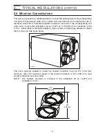
Страница 29: ...dard à 3 trous avec une mise à la terre doit être accessible à moins de 3 pieds de l appareil VH0053 Grâce à notre transition Tandem et à la bouche extérieure double un seul trou est requis dans la paroi extérieure de la maison ce qui simplifie l installation Ces deux pièces font partie de la trousse d installation n 15273 non incluse NOTES 1 Voir le point 2 3 CONSIDÉRATIONS D INSTALLATION en page...

Страница 30: ...eil Aussi installer ces adaptateurs si les trousses d installation nos 15273 ou EA20130 non offertes aux É U sont utilisées Se servir de 4 vis incluses par bouche Voir l illustration ci dessous La distance requise entre les solives pour l installation de la transition Tandem est d au moins 9 po 248 mm La hauteur maximale de cette transition Tandem est de 8 po 222 mm Voir l illustration ci dessous ...

Страница 31: ...e à la terre 3 1 EMPLACEMENT ET INSTALLATION DE L APPAREIL Un tournevis Phillips n 2 ou Robertson n 2 Des ciseaux ou un couteau pour couper le ruban adhésif en toile et les conduits flexibles Du ruban adhésif en toile Une scie va et vient Des ciseaux à tôle si le revêtement de la maison est en aluminium ou en vinyle Un burin et un marteau si le revêtement extérieur de votre maison est en brique Un...

Страница 32: ...n d air vicié et l autre extrémité à la bouche d aspiration d air vicié à l aide de colliers de serrage et de ruban adhésif en toile 3 5 INSTALLATION DES CONDUITS DE 6 PO ET DES GRILLES AVERTISSEMENT Ne jamais installer une grille d évacuation dans une pièce où se trouve un appareil de combustion tel qu une fournaise un chauffe eau à gaz ou un foyer 3 5 1 CONDUIT D ÉVACUATION D AIR VICIÉ Installer...

Страница 33: ... maison 1 2 A VA0033 BUNGALOW Cage d escalier du sous sol A Fermée Une grille d évacuation d air vicié 1 au niveau habité le plus haut de la maison et une grille de distribution d air frais 2 au plus bas niveau habité de la maison Utiliser une grille de plancher pour compenser la fermeture de la cage d escalier 1 2 A VA0034 BUNGALOW Cage d escalier du sous sol A Ouverte centrale Deux grilles d éva...

Страница 34: ...ison 1 1 2 A VA0036 COTTAGE Cage d escalier A Ouverte Deux grilles d évacuation d air vicié 1 aux niveaux les plus élevés de la maison et une grille de distribution d air frais 2 au plus bas niveau habité de la maison 1 1 2 A A VA0037 COTTAGE Cage d escalier A Ouverte en partie fermée en d autres endroits B Une grille d évacuation d air vicié 1 au niveau le plus élevé de la maison et une grille de...

Страница 35: ...rocéder comme suit pour raccorder les conduits flexibles isolés aux bouches de l appareil évacuation d air vicié et aspiration d air frais a Tirer sur l isolant pour exposer le conduit flexible b À l aide d un collier de serrage relier le conduit flexible intérieur à la bouche c Sceller soigneusement le joint avec du ruban adhésif en toile d Tirer l isolant au dessus du joint e Recouvrir le joint ...

Страница 36: ...en toile jusqu à étanchéité complète Voir les figures ci dessous VJ0025 VJ0022 VJ0023 VJ0024 1 2 3 4 CONDUIT D ÉVACUATION D AIR VICIÉ À LA SECTION SUPÉRIEURE 12 3 7 1 TRANSITION TANDEM AVEC LA BOUCHE EXTÉRIEURE DOUBLE SUITE ATTENTION Toujours relier le conduit d évacuation d air vicié à la section supérieure de la transition Tandem La bouche extérieure double est en pièces détachées À l aide des 2...

Страница 37: ...SITION TANDEM AVEC LA BOUCHE EXTÉRIEURE DOUBLE SUITE VD0083F 18 po 457 mm AVERTISSEMENT S assurer que la bouche est à une distance d au moins 6 pi 1 8 m ou plus selon les codes et standards du bâtiment en vigueur des sources de contamination telles que Sortie de fournaise haut rendement Sortie de toute source de combustion Sortie de compteur de gaz barbecue à gaz Poubelle VD0084 1 ATTENTION La tra...

Страница 38: ...upilles de retenue et sceller soigneusement avec du ruban adhésif en toile 3 Appuyer la plaque de la bouche extérieure au mur À l aide des 4 vis n 8 x 1 2 po la fixer au mur Sceller le contour avec du calfeutre 4 Appuyer la bouche extérieure double assemblée sur sa plaque et la visser avec 2 vis n 8 x 3 4 po VD0085 ATTENTION La plaque de bouche extérieure doit être installée de façon telle que le ...

Страница 39: ...le de 6 pieds 1 8 m entre les bouches pour éviter toute contamination Voir l illustration ci dessous 15 ATTENTION Vu son design particulier la bouche extérieure double doit être utilisée uniquement comme sortie d air vicié lors d une installation utilisant 2 bouches extérieures Se servir de la bouche extérieure simple pour l entrée d air frais VD0094 SORTIE D AIR VICIÉ 4 PO 102 MM 6 PI 1 8 M 6 PI ...

Страница 40: ...t avec du ruban à conduit A Tirer l isolant au dessus du joint Tirer le coupe vapeur par dessus l isolant et par dessus l anneau extérieur de la plaque de la bouche extérieure Recouvrir soigneusement le joint avec du ruban à conduit jusqu à étanchéité complète B 3 Appuyer la plaque de la bouche extérieure au mur À l aide des 4 vis incluses la fixer au mur Sceller le contour avec du calfeutre 4 App...

Страница 41: ...te Tirer sur l isolant pour exposer le conduit flexible et passer chacun des conduits flexibles à travers leur trou respectif 2 À l aide des vis fournies assembler le conduit flexible à l anneau de la grille de soffite Sceller soigneusement l aide de ruban adhésif en toile Assembler les grilles au soffite VD0160 6 PI 1 8 M VI0014 AVERTISSEMENT S assurer que la grille d aspiration est à une distanc...

Страница 42: ...use jeter la plaque arrière 2 3 Prendre un bout du fil et le passer à travers la plaque arrière de la commande ou dans la boîte de raccordement ou la plaque de fixation 4 Dégainer le fil de la commande pour accéder aux 4 fils Retirer la gaine des 4 bouts de fils À chacun des fils faire une boucle avec la partie dénudée et les relier à leur vis correspondante Brancher le fil JAUNE à la vis Y le fil...

Страница 43: ... la commande 2 Gaine 3 Passe fils 4 COMMANDE MURALE SUITE 4 1 INSTALLATION DE LA COMMANDE MURALE SUITE 19 VC0052 VC0051 1 2 3 4 5 2 3 4 1 ATTENTION Tenir le câblage basse tension de la commande à une distance d au moins 1 pi 305 mm des moteurs ballast d éclairage circuit gradateur d éclairage et panneau de distribution de courant Ne pas faire cheminer le fil de la commande murale le long du cablâg...

Страница 44: ...ITION NORMAL OU BOOST TÉMOIN LUMINEUX FILTER MAINTENANCE CLIGNOTE LORSQU IL EST TEMPS D EFFECTUER L ENTRETIEN BI ANNUEL VOIR LA SECTION 5 S ALLUME LORSQU IL EST TEMPS D EFFECTUER L ENTRETIEN ANNUEL VOIR LA SECTION 5 RECIRCULATION L APPAREIL FONCTIONNE EN VITESSE NORMALE SANS ÉCHANGE D AIR AVEC L EXTÉRIEUR BOOST L APPAREIL FONCTIONNE EN HAUTE VITESSE TROU POUR LA MISE À ZÉRO RESET FILTER UNE FOIS L...

Страница 45: ...male c est à dire lors de conditions extrêmes momentanées telles que partys présence de fumeurs etc RECIRCULATION Glisser le bouton sur cette position pour un fonctionnement en vitesse normale sans échange d air avec l extérieur Ce mode est recommandé par temps très humide pluie vague de chaleur Aussi l utiliser lorsque l air intérieur est trop sec ou lorsque la température extérieure est très fro...

Страница 46: ... Cependant le cadre d aluminium risque de ternir 3 Rebrancher l appareil 4 Réinitialiser l indicateur d entretien des filtres en insérant une petite tige ex trombone à l intérieur du trou de remise à zéro du filtre de la commande murale Presser délicatement jusqu à ce que le témoin lumineux de l entretien du filtre s éteigne 5 1 ENTRETIEN BI ANNUEL 5 ENTRETIEN AVERTISSEMENT Risque de chocs électri...

Страница 47: ...lateau du haut Cependant le cadre d aluminium risque de ternir 3 Vérifier la bouche extérieure d entrée d air frais S assurer qu il n y ait pas de feuille de brindilles de glace ou de neige qui pourraient être aspirées dans l appareil Nettoyer au besoin 4 Rebrancher l appareil 5 Réinitialiser l indicateur d entretien du filtre en insérant une petite tige ex trombone à l intérieur du trou de remise...

Страница 48: ...Centre de service approuvé le plus près de chez vous Vous pouvez aussi joindre le département de Service à la clientèle aux numéros de téléphone suivants Exclusivement pour le modèle AE60 1 800 637 1453 Exclusivement pour le modèle EA1500 1 800 567 3855 Exclusivement pour le modèle HV 1 5 1 866 737 7770 PROBLÈMES SOLUTIONS 1 L appareil ne fonctionne pas en vitesse Normal ou Boost Vérifier le fusib...

Отзывы: