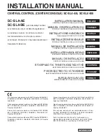
11
FLOOR
SUB-FLOOR
2
9
/
16
"
3
1
/
16
"
INLET
EXTENSION
FLOOR
INLET
FRAME
MOUNTING
BRACKET
SEAL
FLANGED
FITTING
FIGURE 36
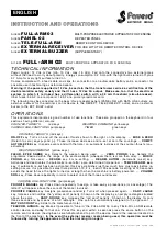
CUT TO
LENGTH
EXTENSION
SLEEVE
FLANGED
FITTING
MOUNTING
BRACKET
FLANGE
FIGURE 37
WALL
INLET
EXTENSION SLEEVE
BRACKET
FLANGED FITTING
TUBING
FIGURE 38
FINAL SYSTEM CHECK
Be sure all inlets are closed and soil bag is in place. Check
switch on power unit for manual on/off operation.
Check each wall inlet to be sure contacts activate power unit
when hose is inserted. A short piece of wire can be used to
short contacts in wall inlet together to activate power unit. Check
each wall inlet and tubing connection for air leaks. Check power
unit for leaks around inlet tube and dirt receptacle.
Installer, will you please make sure a bag is installed in the
power unit. Remove the extra bag and owner's manual from the
power unit dirt receptacle and leave them with the cleaning
attachments for the convenience of the Home Owner…
Thank You.