5.2 Top installation tips to ensure the best results from your CVD Damper
Airflow
CVD100 Damper
Damper outlet
Rigid ducting
500mm min
300mm min
Rigid ducting
Damper inlet
Flexible ducting
Flat ducting
Airflow
CVD100 Damper
Multiple ducting bends
Airflow
CVD100 Damper
Damper outlet
Damper inlet
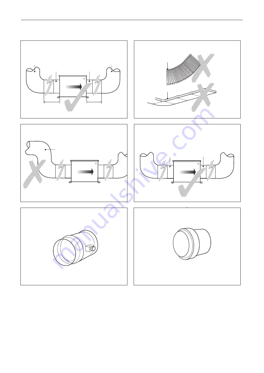
Fig. 6.1. Fit at least 500mm of straight
RIGID
ducting at the
damper inlet and 300mm of straight RIGID ducting at the damper
outlet before connecting to any
RIGID
ducting bends, or grilles.
Fig. 6.2.
Do not
use flexible or flat ducting.
Fig. 6.3.
Avoid multiple bends
near the inlet side of the
CVD Damper.
Fig. 6.4. Please note the damper orientation. This must correspond
to the direction of the airflow when installing the damper.
Fig. 6.5.
Avoid balancing dampers or other devices
that create
a jet upstream of the inlet to the CVD Damper.
Fig. 6.6. If Air valves with screw-in adjustments are used
ensure they are set up with maximum opening.
Installation and Maintenance
CVD Constant Volume Dampers
3
10. 05. 17. Leaflet Number 671638


