


39
30. 07. 20. Document Number 671760
Nuaire |
Western Industrial Estate
|
Caerphilly
|
CF83 1NA
|
nuaire.co.uk
BPS V-CO
Installation Manual
32
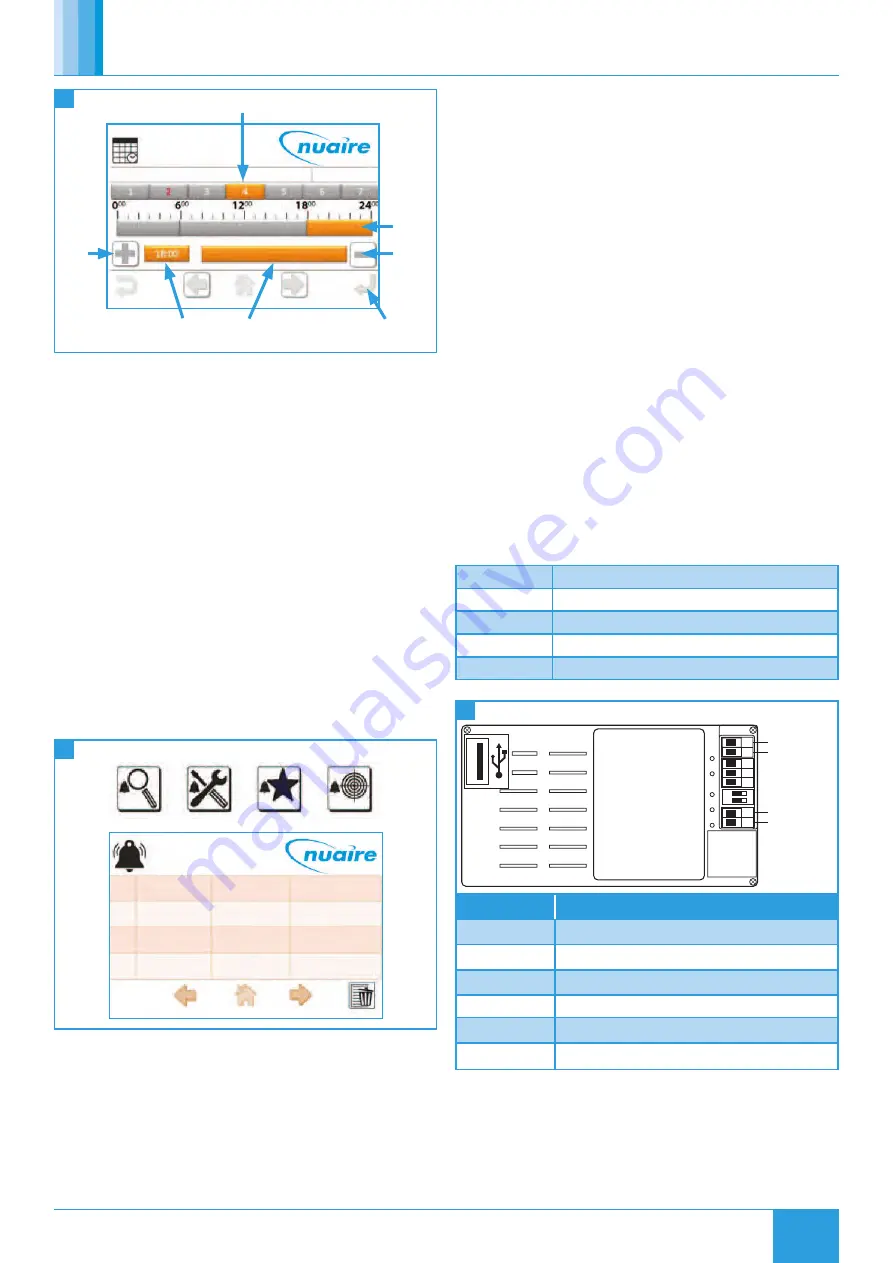
Setting Schedules
Time Schedule
10-10-15
15.39
OFF
ON
ON
OFF
Add
Period
Selected Period’s
Time & State
Save Change
Remove
Selected
Period
Selected
Period
Selected Day
9.7.6 Alarm Log
When an XBC alarm changes state, a signal is sent to the LCD
display and logged on the alarm page. If there are items on the
alarm page the standard top left page icons change to one of the
following, depending on the current page. The alarm page can be
accessed by selecting the alarm icon.
Alarm events are logged with a date and time:
•
‘Nor’
represents a change to a normal state.
•
‘Ala’
represents a change to an alarm state.
•
The text in parentheses denotes the alarm the event applies to.
The log can hold up to 40 events.
Logged alarm events can be deleted by using the delete icon. If all
events are deleted, alarm states can still be checked by navigating
to the BACnet alarm objects via the network browser page. See the
BACnet alarm list for alarm objects.
The LCD can be set to sound a continuous beep when a new item is
added to the alarm log. This beep is silenced by any user interaction,
but the alarm event is still logged. This option can be changed via the
settings page.
1 / 1
2
1
Nor(A CIR 2)
Ala(A Cir 2)
Nuaire BPS
09:47 16-10-15
09:44 16-10-15
Nuaire BPS
33
Alarm Log
9.7.7 Backup
The LCD settings, favourites and locked items can be backed up to a
USB drive by plugging a USB into the rear of the LCD. The screen will
automatically change to a download screen. Select the item required
and choose upload.
To download data to the LCD select the data type and choose
download.
If a user or service password is forgotten, they can be reset by
re-downloading a backup file to the LCD that has no set password. It is
recommended that a backup is made of a LCD with no password set.
9.8 Multiple Controllers
When accessing the Network View the FAD launches a Network
Discovery function. The purpose of this function is to find other BACnet
devices residing on the same MS/TP trunk. The maximum number of
devices supported by the FAD discovery function is 32.
9.9 Controller Wiring
There are 2 ways of connecting the LCD controller:
•
Connected to the FC bus using screwed terminals. A separate
power supply is required.
•
If the controller is standalone, the LCD display can be connected
to the RJ12 FC bus port on the front of the FAC controller. This
FC port will also power the LCD, so in this case, a separate power
supply is not required. One of the following cables is required to
achieve this:
ESCO-LCD-3M
Ecosmart-Connect LCD RJ12 Connection Cable 3m
ESCO-LCD-5M
Ecosmart-Connect LCD RJ12 Connection Cable 5m
ESCO-LCD-10M
Ecosmart-Connect LCD RJ12 Connection Cable 10m
ESCO-LCD-20M
Ecosmart-Connect LCD RJ12 Connection Cable 20m
ESCO-LCD-30M
Ecosmart-Connect LCD RJ12 Connection Cable 30m
ON
+
-
+
-
12...24 VAC
12...24 VAC
BACnet
MS/TP
1
2
3
4
5
6
7
1 2
34
Controller Wiring
Terminals
Description
1-3
Unused
4
Power Supply (-) 12...24 VAC / VDC
5
Power Supply (+) 12...24 VAC / VDC
6
BACnet MS/TP Port (RT-)
7
BACnet MS/TP Port (RT+)
Programming USB Port
DIP Switch 1
BACnet MS/TP Line Terminator (End of Network
120Ω resistor switch)
DIP Switch 2
Unused


