background image


Trinity


Installation and Operation Instructions  

Tft Series 


64 


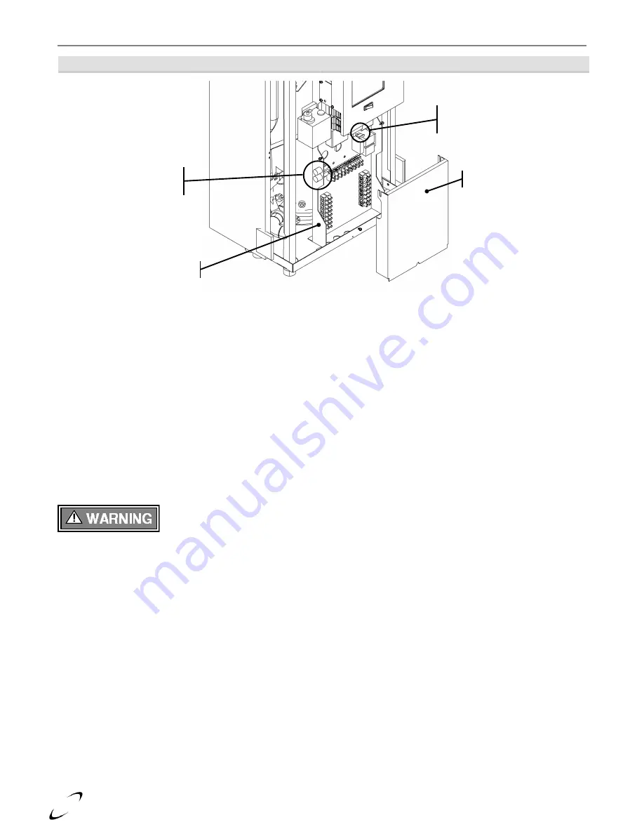
Figure 16-1  Tft Control Panel


Figure 14-1  Tft Model 


Fuses 

The Trinity  Tft  is equipped  with  three  (3)  fuses.  Check  these  fuses before replacing  the  controller  or  any other 
electrical component; if the fuse is blown, it will prevent the protected device(s) from functioning.  


To check, and if necessary replace, the fuses: 


Remove all 120VAC power from the appliance. Be careful to check that the unit is not powered from more 
than one source e.g. a UPS (uninterruptible power supply). 


Remove the front cover. 


Fuses "A" and "B" are accessible by removing the spring-loaded knurled knob of their respective holders. 
Push the knob toward the panel, and twist approximately 1/4 turn counter-clockwise. 


Fuse  "C"  is  an  auto  blade  type  and  is  installed  in  an  “inline”  fuse  holder;  gain  access  by  removing  the 
control panel cover. 


After inspecting and if necessary replacing fuses, replace the panel cover and front cover. Restore power to the 
appliance and confirm proper operation. 


Only replace fuses with identical parts, see Figure 16-1.  Failure to follow this warning 
may result in component failure, fire, property damage, serious injury or death. 
 

User Interface (Touch-screen Display) 

A blank screen does not necessarily indicate a problem; the display may be configured to automatically blank the 
screen after a pre-set interval. Simply touch the screen to activate it. Confirm that 120VAC is being supplied to 
the  appliance  and  that  the  service  switch  located  below  the  display  is  turned  ON  (1).  If  the  screen  does  not 
become active, perform the following procedure: 


Blank Screen 

1.


Remove the front cover from the boiler. 

2.


Remove  the  control  panel  cover  and  check  Fuse  “C”  (Auto  Blade  Type);  if  faulty  check  for  shorts  in  the 
thermostat wiring, correct, then replace fuse (see Figure 16-1).  

3.


Ensure the “2 by 2” Molex connector, located behind the display at the top, is connected and that the wires 
are  fully  inserted  (see  Figures  16-2  and  16-3).    Verify  that  24VAC  is  present  between  the  Blue  and  Red 
wires; if not trace wiring back to 24VAC transformer; correct wiring and/or replace transformer (see Figure 
13-1). 

4.


Remove the display assembly from the control panel and check the 24VAC wiring connection on the back of 
the display; Blue to terminal 7 [24VAC (COM)], Red to terminal 8 [24VAC] (see Figure 16-3).     


Fuse “C” ATO 2A 
32V Auto Blade Type 

Fuses “A” and “B” 3AG 

7A 250 Fast-Acting 

Control Panel Cover 

Control Panel 

Содержание Trinity Tft110

Страница 1: ...ST 86 HAZARD SYMBOLS AND DEFINITIONS Danger Sign Indicates a hazardous situation which if not avoided will result in serious injury or death Warning Sign Indicates a hazardous situation which if not avoided could result in serious injury or death Caution Sign plus Safety Alert Symbol Indicates a hazardous situation which if not avoided could result in minor or moderate injury Caution Sign without ...

Страница 2: ...not try to light the burner by hand 4 Turn the manual gas valve to the OFF position Remove front access panel 5 Wait five 5 minutes to clear out any gas Then smell for gas including near the floor If you smell gas STOP Follow B in the safety information above If you don t smell gas go to the next step 6 Turn the manual gas valve ON Wait an additional five 5 minutes smelling for gas 7 Replace the f...

Страница 3: ...ystem that serves the same function THIS OVERRIDE MUST NOT BE USED UNLESS AT LEAST ONE OF THE FOLLOWING CONDITIONS IS TRUE An external energy management system is installed that reduces the boiler water temperature as the heating load decreases This boiler is not used for any space heating This boiler is part of a modular or multiple boiler system having a total input of 300 000 BTU hr or greater ...

Страница 4: ... 52 5 2 mm Tft154 85538 1 See Note 1 Tft201 85801 1 See Note 2 Tft285 85802 1 5 2 mm Tft399 pre s n 20916 3 84471 1 74 7 4 mm Tft340 399 post s n 90974 4 85469 1 6 75 mm Notes 1 The Tft154 is converted to Propane using a replacement LP Venturi Insert p n 85463 not an LP Orifice Follow the Natural Gas to LP Conversion Instructions provided with kit number 85538 1 2 The Tft201 is converted to Propan...

Страница 5: ...gn shall read in print size no less than one half 1 2 inch in size GAS VENT DIRECTLY BELOW KEEP CLEAR OF ALL OBSTRUCTIONS plate included with boiler 4 INSPECTION The state or local gas inspector of the side wall horizontally vented gas fueled equipment shall not approve the installation unless upon inspection the inspector observes carbon monoxide detectors and signage installed in accordance with...

Страница 6: ...e only vent materials and methods detailed in these instructions Wall mounting of unit requires two people to lift the boiler into place Failure to follow these instructions may result in property damage or personal injury High Altitude Operation The Trinity Tft is designed to operate at its maximum listed capacity in installations located at 0 2000ft above Sea Level Since the density of air decre...

Страница 7: ...e Table 4 4 for a list of approved materials Under all circumstances the minimum clearances listed in Table 3 1 must be provided Indoor Combustion Air When using Indoor Combustion Air in lieu of Direct Vent air inlet piping provisions for combustion and ventilation air in accordance with section Air for Combustion and Ventilation of the National Fuel Gas Code ANSI Z223 1 NFPA 54 U S or Clause 8 2 ...

Страница 8: ...oved CPVC Polypropylene or Stainless Steel vent and air inlet pipe and fittings see Table 4 4 PVC is not permitted Failure to follow these instructions may result in damage or serious injury Figure 3 1 Closet Installation Minimum Clearances Model Tft60 110 Shown Ventilation Air Openings are not required if the boiler area meets the Recommended Clearances listed in Table 3 1 Bottom ventilation open...

Страница 9: ...holes on the bottom flange pointed upward and angled away from the wall Mount the appliance to the wall by aligning the Upper bracket A with the Wall mount bracket B Slide the Upper bracket down over the wall mount bracket until it hooks Once the appliance is resting securely on the Upper bracket secure the Bottom bracket C to the underside of the appliance using the mounting hardware removed in S...

Страница 10: ...g system Steps to Removing an Existing Boiler 1 Seal any unused openings in the common venting system 2 Visually inspect the venting system for proper size and horizontal pitch Verify that there is no blockage restriction leakage corrosion or other deficiencies which could cause an unsafe condition 3 Insofar as is practical close fireplace dampers all building doors and windows and all doors betwe...

Страница 11: ...ontaminated Sources to Avoid Antistatic fabric softeners bleaches detergents cleaners Laundry facilities Perchloroethylene PCE hydrocarbon based cleaners Dry cleaning facilities Chemical fertilizer herbicides pesticides dust methane gas Farms or areas with livestock and manure Paint or varnish removers cements or glues sawdust Wood working or furniture refinishing shops Water chlorination chemical...

Страница 12: ...ter The manufacturer recommends using two elbows to create a swing joint to reduce potential strain on vent piping and cemented joints See Figures 4 3 through 4 5 for illustrations Gasket Seating Improper seating can cause leakage and eventual failure of the sealing gasket Ensure the vent pipe is properly beveled prior to installation and that the pipe is fully inserted into the boiler flue adapte...

Страница 13: ...ISANY0303 Z Flex Z Dens 2ZDCPVCG3 Stainless Steel DuraVent FasNSeal 300715 Z Flex Z Vent 2SVSTTA03 Tft340 399 Polypropylene DuraVent PolyPro 300151 Centrotherm InnoFlue ISAA0404 Z Flex Z Dens 2ZDCPVCG4 Stainless Steel DuraVent FasNSeal 303631 Z Flex Z Vent 2SVSTTA04 5 Notes 1 Listed appliance adapters are only approved for use with the respective venting brand i e a PolyPro appliance adapter shall...

Страница 14: ...PVC Exhaust Vent Swing Joint to attain slope in horizontal runs Air inlet Pipe Air Inlet Adapter factory supplied PVC Coupling Air Inlet Adapter factory supplied Swing Joint to attain slope in horizontal runs PVC Exhaust Vent check local codes and Table 4 3 Mandatory Vent Pipe Transition Pipe See Table 4 2 Air inlet Pipe CPVC Transition Pipe minimum 5 long factory supplied Flue Outlet Adapter fact...

Страница 15: ...iping must be readily accessible for inspection Flue Outlet Adapter factory supplied SS Exhaust Vent Swing Joint to attain slope in horizontal runs SS Air inlet Pipe SS Appliance Adapter see Table 4 3 Air Inlet Adapter factory supplied Air inlet Adapter factory supplied PPS Elbow w offset angle to account for slope PPS Exhaust Vent PPS Air inlet Pipe PPS Appliance Adapter see Table 4 3 Flue Outlet...

Страница 16: ... metallic vent pipe and fittings with thermal insulation is prohibited Failure to follow these instructions may result in property damage personal injury or death Vent Air inlet Pipe Length Determination Use Table 4 5 to determine the maximum pipe length that can be used The table calculates 90º elbows and 45º elbows at 5 equivalent feet each Example When using 3 pipe a Tft60 285 can be installed ...

Страница 17: ...ty damage or where condensate or vapor could cause damage or could be detrimental to the operation of regulators relief valves or other equipment Extra precaution must be taken to adequately support the weight of the Vent Air inlet piping in applications using roof top terminations Failure to follow these instructions may result in venting or boiler component failure resulting in flue gas spillage...

Страница 18: ...pproved 3 Clearance requirements in this manual supersede those of the instructions included with the vent terminal 4 Piping MUST be secured to the vent terminal during installation 5 IPEX Concentric Terminal MUST be cemented together and to the vent pipes during installation 6 Vent Screens provided with boiler may be used with the IPEX Concentric Vent Kits otherwise use IPEX vent screens 2 vent s...

Страница 19: ...ic Termination Sidewall Location of exhaust and air inlet connections vary between models see Figure 4 3 model Tft60 110 shown Exhaust Inlet Location of exhaust and air inlet connections vary between models see Figure 4 3 model Tft60 110 shown Exhaust Inlet Location of exhaust and air inlet connections vary between models see Figure 4 3 model Tft60 110 shown Exhaust Inlet Location of exhaust and a...

Страница 20: ... exhaust Sidewall inlet Location of exhaust and air inlet connections vary between models see Figure 4 3 model Tft60 110 shown Location of exhaust and air inlet connections vary between models see Figure 4 3 model Tft60 110 shown Exhaust Inlet Location of exhaust and air inlet connections vary between models see Figure 4 3 model Tft60 110 shown Exhaust Inlet Exhaust Inlet Location of exhaust and a...

Страница 21: ...to documentation included with termination kit for complete installation instructions Min 12 above grade or snow level Exhaust Air inlet Exhaust Air inlet around perimeter Min 12 above grade or snow level Exhaust center Air inlet bottom Exhaust Air inlet Gas Vent Directly Below Keep Free of Obstructions Exhaust Air inlet Min 12 above grade or snow level Vertical Min 18 Horizontal 4 12 or greater t...

Страница 22: ...n 36 Flashing Min 12 above grade or snow level Vent Screen Vent pipe piece to retain vent screen Exhaust center Air inlet around perimeter Flashing Refer to documentation included with termination kit for complete installation instructions Refer to documentation included with termination kit for complete installation instructions Min 12 above grade or snow level Flashing Exhaust Air inlet Figure i...

Страница 23: ...r a minimum of 1 4 per linear foot of vent 6 25 mm per linear 305 mm For applications where excessive condensation is possible 1 2 per linear foot 13 mm per linear 305 mm is recommended 9 Vent Supports Where required Vent and Air inlet piping shall be secured to the wall for more rigidity All interior vent pipe shall be supported a minimum of every 36 915 mm 10 Roof Exhaust In all roof application...

Страница 24: ...oped back to the boiler 1 2 elevation for every linear foot 13 mm for every linear 305 mm Figure 4 10 Existing Chimney Chase Way It is permissible to use an existing chimney as a chase way to run the Vent Air inlet piping as long as 1 The chimney is not being used by any other boiler 2 Flue gases don t enter the vacant chimney 3 Only Trinity certified venting materials are used see Section 4 0 4 V...

Страница 25: ...ot on public property if adjacent 12 7 ft 2 13 m 7 ft 2 13 m R Above a public walkway X X X X S Above a sidewalk or paved driveway that is located between two single family dwellings and services both dwellings X X X X T Under a concrete veranda porch deck or balcony 7 24 in 610 mm 24 in 610 mm U Above under or near exterior stairs X X X X V Into a canopy or carport X X X X Notes 1 Canadian instal...

Страница 26: ...learances Figure 5 2 Sidewall Termination See Table 5 1 G Letter represents a specific Termination Position Refer to Table 5 1 for corresponding termination clearances Concentric Vent Termination Q Two Pipe Termination F Clearance Q Adjacent to Public Walkway or Driveway Minimum 7ft 2 13 m G Clearances F and G Canada Minimum 3 ft 915 mm The US Minimum 1 ft 305 mm ...

Страница 27: ...nsate Trap is factory supplied with the boiler and must be field installed 1 Inspect Condensate Trap Assembly Inspect the Condensate Trap to ensure all parts were shipped with the assembly see Figure 6 1 The Condensate Trap must be periodically disassembled and cleaned as part of a regular maintenance plan 2 Attach Corrugated Outlet Tube Remove the Outlet Retaining Nut and Outlet Gasket and slide ...

Страница 28: ...e 6 1 Condensate Drain Piping Inlet Gasket Outlet Corrugated Outlet Tube Outlet Retaining Nut Outlet Gasket Inlet Cleanout Cap Condensate Trap Inlet Retaining Nut firmly tightened Corrugated Outlet Tube routed to household drain condensate pump or neutralizer no strain applied on tubing or condensate drain assembly ...

Страница 29: ...60 85 82650 1 415 4 15mm Tft285 85802 1 5 2mm Tft110 82650 1 52 5 2mm Tft399 pre s n 20916 3 84471 1 74 7 4mm Tft154 85538 1 See Note 1 Tft340 399 post s n 90974 4 85469 1 6 75mm Tft201 85801 1 See Note 2 Notes 1 The Tft154 is converted to Propane using a replacement LP Venturi Insert p n 85463 not an LP Orifice Follow the Natural Gas to LP Conversion Instructions provided with kit number 85538 1 ...

Страница 30: ...er doping or applying dope to the female end can result in a blocked gas line DO NOT TIGHTEN FITTINGS WITHOUT SUPPORTING THE GAS VALVE as damage to the valve or blower motor can occur Install a manual Equipment Shut Off Valve as shown in Figure 7 1 Valve must be listed by a nationally recognized testing laboratory The gas line piping can safely be removed from the boiler for servicing by strategic...

Страница 31: ...jury or death Manual Gas Shutoff Valve Should overheating occur or the gas supply fail to shutoff close the Manual Gas Shutoff Valve to the boiler Union Flexible Gas Line Piping Recommended to eliminate strain on the boiler gas components only use if acceptable by local codes Drip Leg Optional Gas Supply Location When used as the Gas Supply Location remove cap and install on the top fitting drip l...

Страница 32: ...ny electric switch Do not use any phone in your building Immediately call your gas supplier from a neighbor s phone Follow the gas supplier s instructions If you cannot reach your gas supplier call the fire department C Use only your hand to turn the gas shutoff valve Never use tools If the handle will not turn by hand don t try to repair it call a qualified service technician Force or attempted r...

Страница 33: ...the flame sensor recycle power and reconfirm proper lighting The flame probe is located in the burner plate it has a single white semi transparent wire connected to it DO NOT remove the orange spark cable from the ignition electrode also located in the burner plate this device is used for spark ignition and produces 14 000 volts potential which would result in an EXTREME ELECTRICAL SHOCK possibly ...

Страница 34: ...ith Table 9 1 The pressure will be lowest during the maximum flow of gas 7 Adjust the gas line pressure to ensure the parameters in Table 9 1 are attained under all conditions If possible adjust the line pressure to the Nominal Desired value listed in Table 9 1 while the unit is operating at the maximum modulation rate see Table 9 2 8 Continue observing the gas line pressure until the completion o...

Страница 35: ...n serious injury or death Adjustment Throttle Input Screw Adjustments The boiler is equipped with a Throttle Input Adjustment Screw located on the Gas Valve It is used to adjust the flow of gas leaving the gas valve entering the Venturi and then the combustion air stream Turn the Throttle screw in clockwise to reduce the flow of gas make combustion leaner and reduce the concentration of CO2 in the...

Страница 36: ...this section may result in erratic and unreliable burner operation leading to reduced efficiency increased fuel consumption reduced component life heat exchanger combustion deposits and general unsafe operation Failure to follow these instructions may result in serious injury or death Analysis Perform flue gas analysis and adjust throttle input screw as required until CO2 and CO levels are within ...

Страница 37: ...01 Gas Valve Adjustment Figure 9 3 Tft285 399 Gas Valve Adjustment Tft340 399 Illustrated Throttle Input Adjustment Screw Line Pressure Test Port DO NOT Adjust Gas Valve Throttle Input Adjustment Screw Line Pressure Test Port DO NOT Adjust Gas Valve Remove access cover adjust from top ...

Страница 38: ...tic dirt separators on systems containing large amounts of iron Use Dirt Separators to remove debris from system water Where possible treat boiler feed water Repair system leaks immediately to prevent oxygen air and untreated water from entering the system Proper equipment must be used to test the water Digital meters are highly recommended because they can be calibrated The use of test strips is ...

Страница 39: ...tem for cleaning or sealing Inhibitors should be used for all installations in both new and existing heating systems Follow the instructions provided by the inhibitor manufacturer when adding it to the system to ensure the correct concentration A list of approved inhibitors is provided below Rhomar Pro tek 922 Sentinel X100 Fernox Protector F1 Table 10 1 Boiler System Cleansers and Corrosion Inhib...

Страница 40: ...ectly above the outlet fitting on the top of the unit see Figures 10 1 through 10 3 illustrating the correct location Open the auto air vent s vent cap to promote the removal of air during commissioning of the boiler and to avoid malfunctioning of the LWCO Once the air is removed from the system close the vent cap to prevent water from leaking onto the boiler Low Water Cutoff LWCO Tft boilers are ...

Страница 41: ...ress Temp Gauge factory Supplied Pressure Relief Valve alt location check local installation codes Inlet Outlet Auto Air Vent factory Supplied Pressure Relief Valve factory Supplied Press Temp Gauge factory Supplied Pressure Relief Valve alt location check local installation codes Outlet Inlet Pressure Relief Valve alt location check local installation codes Press Temp Gauge factory Supplied Press...

Страница 42: ...ressure Relief Valve alt location check local installation codes Press Temp Gauge factory Supplied Outlet Inlet Auto Air Vent factory Supplied Pressure Relief Valve factory Supplied Pressure Relief Valve alt location check local installation codes Press Temp Gauge factory Supplied Inlet Outlet Auto Air Vent factory Supplied Pressure Relief Valve factory Supplied Pressure Relief Valve alt location ...

Страница 43: ...ressure Relief Valve alt location check local installation codes Press Temp Gauge factory Supplied Inlet Outlet Auto Air Vent factory Supplied Pressure Relief Valve factory Supplied Pressure Relief Valve alt location check local installation codes Press Temp Gauge factory Supplied Outlet Inlet Auto Air Vent factory Supplied Pressure Relief Valve factory Supplied Pressure Relief Valve alt location ...

Страница 44: ...r Pump C in Figure 10 5 Zone Circulators in Figure 10 6 Central Air Removal Devices i e Micro Bubbler or Air Scoop Pressure Regulating Fill Valve Backflow Preventer Expansion Tank Circulating Pumps Trinity Tft boilers are equipped with three 120VAC pump outputs 1 PUMP A DHW Pump operates during a Domestic Hot Water demand DHW 2 PUMP B Boiler Pump operates during any demand 3 PUMP C CH Pump operate...

Страница 45: ...99 0015 MS E7 25 11 3 9 1 1 4 NRF 22 UPS15 58 0015 MS Astro 30 35 8 3 1 1 NRF 22 UPS15 58 0015 MS Astro 30 Tft201 20 18 7 5 1 1 2 NRF 36 UPS26 99 0013 MS E7 25 15 5 8 1 1 4 NRF 36 UPS26 99 0013 MS E7 35 11 3 9 1 1 4 NRF 22 UPS15 58 0015 MS Astro 30 Tft285 20 26 14 1 1 2 NRF 36 UPS26 99 0013 MS E8 25 21 9 8 1 1 2 NRF 36 UPS26 99 0013 MS E7 35 15 5 7 1 1 4 NRF 25 UPS26 99 0015 MS E7 Tft340 20 32 7 9...

Страница 46: ...0 1 2 3 4 5 6 2 4 6 8 10 12 Flow Rate US gpm Head Loss ft Figure 10 4 b Tft154 285 Head Loss Curve 0 2 4 6 8 10 12 14 6 8 10 12 14 16 18 20 22 24 Flow Rate US gpm Head Loss ft Figure 10 4 c Tft340 399 Head Loss Curve 0 2 4 6 8 10 10 12 14 16 18 20 22 24 26 28 30 32 34 36 38 Flow Rate US gpm Head Loss ft ...

Страница 47: ...ter is in series with the boiler during a demand for DHW Therefore its head loss along with the head loss of the boiler and associated piping must be considered when sizing the circulator Figure 10 5 Single System Circulator Configuration Often used in applications zoned with Zone Valves During a demand for central heat the boiler energizes the System Circulator via the Central Heating CH pump out...

Страница 48: ...ting Circulator Figure 10 5 illustrates the basic plumbing requirements for a Trinity Tft boiler installation with a single Central Heating circulator and an Indirect Water Heater Refer to Figures 10 1 through 10 3 for identification of boiler water connections as their locations will vary between boiler models ...

Страница 49: ...ing Circulators Figure 10 6 illustrates the basic plumbing requirements for a Trinity Tft boiler installation with a multiple Central Heating circulators and an Indirect Water Heater Refer to Figures 10 1 through 10 3 for identification of boiler water connections as their locations will vary between boiler models ...

Страница 50: ... the Master parameter enabled becomes the single point of contact for Central Heating Domestic Hot Water and Outdoor Reset settings and control wiring Use the instructions detailed in this section to set up and install the cascade boiler system reference Appendix A Controller and Touchscreen Display Instructions for details on more advanced settings and for assistance with navigating the touchscre...

Страница 51: ...figured as follows Configure Sensor Configuration S10 J10 7 sensor Outdoor Sensor Optional wire the outdoor sensor to SENSOR COM and OUTDOOR of any one of the boilers in the cascade see Field Wiring Table 12 2a and Figure 12 2 Note only one outdoor sensor is needed for the multiple boiler system Modbus Address assign a unique MB2 Modbus Address to each boiler in the cascade Access the MB2 Modbus A...

Страница 52: ...tic Hot Water Tank Thermostat connect to SENSOR COM and DHW of the Master Boiler see Field Wiring Table 12 2a and Figure 12 2 Switch must be an isolated end switch dry contact DHW Setpoint at the Master boiler only set the DHW setpoint via the Lead Lag Master Configuration menu accessed as follows Configure Lead Lag Master Configuration DHW setpoint DHW switch Lead Lag at the Master boiler only se...

Страница 53: ...ft is equipped with two 7 Amp fuses to protect 120VAC system components The fast acting fuses are located on the left side of the control panel and are easily accessed upon removal of the front cover of the boiler cabinet Fuse A Protects the blower spark generator and PUMP B output circuits Fuse B Protects PUMP A and PUMP C output circuits Wire Protection When passing any wiring through the cabine...

Страница 54: ...t to the DHW circulator powered during a demand for DHW PUMP B 3 120VAC output to the Boiler circulator powered during all demands DHW local Central Heat CH1 and Lead Lag Central Heat CH2 LL This output is not used for all plumbing configurations see Section 10 0 PUMP C 4 120VAC output to the Central Heating circulator powered during a demand for local Central Heat CH1 or Lead Lag Central Heat CH2...

Страница 55: ...wall mountable OD Sensor is included with each boiler When connected to terminals 6 and 8 the control will indicate the outdoor temperature and Outdoor Reset function will be operable DHW 9 DHW Tank Demand Input requiring closure of terminals 6 and 9 to initiate a demand for DHW Switch made via isolated end switch dry contact from a thermostat aquastat located in an Indirect Fired Water Heater Or ...

Страница 56: ...l other than terminals 4 5 and 6 LIM CH1 and CH2 LL Failure to follow these instructions may damage the unit The low voltage connections are divided into two separate barrier strips Communication and Sensor I O Input Output and 24VAC I O DO NOT connect 24VAC or other power supply to the Communication and Sensor I O connections doing so will cause control failure Figure 12 2 Low Voltage Field Wirin...

Страница 57: ...s for the purpose of staging cascading as many as 8 boilers can be daisy chained together For lone boiler applications this port can be alternatively used for communication to an external device i e Building Automation System BAS Controller communication port MB2 is factory wired to Low Voltage field connections DATA DATA and DATA COM see Figure 12 2 3 Display COM2 the new Tft touch screen display...

Страница 58: ...Trinity Installation and Operation Instructions Tft Series 58 13 0 WIRING SCHEMATICS Figure 13 1 Tft Connection Diagram ...

Страница 59: ...Tft Series Installation and Operation Instructions Trinity 59 Figure 13 2 Tft Ladder Logic Diagram ...

Страница 60: ...us injury or death 1 Turn gas shut off valve to the ON position 2 Turn Power on to the boiler 3 Set Controller to the desired settings 4 Turn thermostat up Ignition will occur Operational Checklist 1 System is free of gas leaks 2 System is free of water leaks 3 Water pressure is maintained above 15 PSI 4 All air is purged from the heating system piping 5 Ensure proper water flow rate unit must not...

Страница 61: ...efore commencing any service work in the combustion chamber Take all necessary precautions and use recommended personal protective equipment as required Cleaning Checklist 1 Remove the demand for heat allow the post purge cycle to finish turn gas and power supply off 2 Working inside the cabinet disconnect the cabling to the combustion blower gas valve spark igniter and flame sensor then remove th...

Страница 62: ...oiler This boiler contains materials that have been identified as carcinogenic or possibly carcinogenic to humans Table 15 1 Handling Instructions for Refractory Ceramic Fibers RCF Reduce the Risk of Exposure Precautions and Recommended Personal Protective Equipment Avoid contact with skin and eyes Wear long sleeved clothing gloves and safety goggles or glasses Avoid breathing in silica dust Wear ...

Страница 63: ... o The thermostat is placed at a sufficiently high setting to create a call for heat to the boiler To check for the presence of 120VAC and 24VAC at the boiler follow this procedure Remove the boiler front cover remove screw from bottom undo side latches then lift cover up and off 120VAC o Remove the control panel cover Loosen the three 8 hex head sheet metal screws securing the cover to the contro...

Страница 64: ...t in component failure fire property damage serious injury or death User Interface Touch screen Display A blank screen does not necessarily indicate a problem the display may be configured to automatically blank the screen after a pre set interval Simply touch the screen to activate it Confirm that 120VAC is being supplied to the appliance and that the service switch located below the display is t...

Страница 65: ...the wiring connections on the back of the touch screen display remove display assembly see Figure 16 3 Green Red and Black go to terminals 1 2 and 3 respectfully Figure 16 2 Touch screen Display Electrical Disconnects Power Supply Connector 2 by 2 Communication Connector 4 by 1 Figure 16 3 Display Electrical Connection Access Red Black Blue Blue White on bottom Red Red Green Green Black White Red ...

Страница 66: ...as applicable Appliance outlet temperature exceeds Setpoint On Hysteresis Check outlet temperature setpoint and hysteresis settings via Touchscreen Hold Delay or Lockout Check Summary page on Touchscreen for code Burner switch off Check Summary page if Demand indicates Burner switch off go to diagnostics burner test page and switch on Lockout 2 Waiting for safety data verification Safety parameter...

Страница 67: ... Incorrect Outlet high limit response setting Unless deemed unacceptable by local installation codes the Outlet high limit response should be set to recycle and hold to prevent lockout Lockout or Hold 81 Delta T limit OR Appliance making banging or hissing sounds Insufficient water flow Check Fuse B Check appliance pump Ensure plumbing is correct Refer to Section 10 0 System Piping Check that wate...

Страница 68: ...ecurely attached to the quick connect tab on the igniter electrode Blocked venting Check for blockage of the exhaust vent air inlet combustion blower gas valve Venturi burner heat exchanger etc Blocked condensate drain Clean condensate trap inspect condensate drain for blockages and build up correct accordingly Insufficient gas line pressure Ensure the manual gas shutoff valve is open Refer to Sec...

Страница 69: ...s of electrical noise i e a large motor or multiple pieces of equipment starting at the same time Failing Limit Switch in ILK circuit Check operation of internal LWCO and or external limit i e devise connected between R and LIM replace as necessary Hardware failure of Sola controller Reset power If problem persists replace Sola controller Alert 206 Lead Lag header temperature was invalid System Se...

Страница 70: ...ltage at terminals J8 1 2 24VAC should be present Blower not operating Blower power disconnected Verify that the 3 position Molex connector on the wiring harness is securely connected to its mating connector on the blower Blown fuse Check Fuse A using the procedure described above Fuse A protects the blower as well as the ignition spark generator and appliance pump Faulty blower Measure voltage ac...

Страница 71: ...ow Hold 21 Internal fault Flame number of sample mismatch Hold 22 Internal fault Flame bias out of range Hold 23 Internal fault Bias changed since heating cycle starts Hold 24 Internal fault Spark voltage stuck low or high Hold 25 Internal fault Spark voltage changed too much during flame sensing time Hold 26 Internal fault Static flame ripple Hold 27 Internal fault Flame rod shorted to ground det...

Страница 72: ...8 Demand lost in run Hold 79 Outlet high limit Hold 80 DHW high limit Disabled 81 Delta T limit Hold Lockout 82 Stack limit Lockout 83 Delta T exchanger outlet limit Disabled 84 Delta T inlet exchanger limit Disabled 85 Inlet Outlet inversion limit See Table 17 1 Hold 86 Exchanger outlet inversion limit Disabled 87 Inlet exchanger inversion limit Disabled 88 Outlet T Rise limit See Table 17 1 Lock...

Страница 73: ...ion Hold Lockout 130 Fan speed failed during ignition Hold Lockout 131 Fan movement detected during standby Hold 132 Fan speed failed during run Hold 133 135 RESERVED 136 Interrupted Airflow Switch failed to close Hold 137 ILK failed to close Hold 138 Flame too low Lockout 139 142 RESERVED 143 Internal fault Flame bias out of range 1 Lockout 144 Internal fault Flame bias out of range 2 Lockout 145...

Страница 74: ...onse setting Lockout 189 Invalid Flame sensor type setting Lockout 190 Invalid interrupted air switch enable setting Lockout 191 Invalid interrupted air switch start check enable setting Lockout 192 Invalid Igniter on during setting Lockout 193 Invalid Ignite failure delay setting Lockout 194 Invalid Ignite failure response setting Lockout 195 Invalid Ignite failure retries setting Lockout 196 Inv...

Страница 75: ...t 240 Invalid Outdoor connector type setting Lockout 241 Exchanger sensor not allowed with stack connector setting Lockout 242 Invalid DHW auto detect configuration Lockout 243 Invalid UV with spark interference not compatible with Igniter on throughout PFEP Lockout 244 Internal fault Safety relay test invalid state Lockout 245 Invalid Outlet connector type setting for T rise Lockout 246 4 20mA ca...

Страница 76: ...tored from factory defaults 15 Safety group verification table was updated 16 Invalid Parameter PCB was detected 17 Invalid Range PCB was detected 18 Alarm silence time exceeded maximum 19 Invalid safety group verification table was detected 20 Backdoor password could not be determined 21 Invalid safety group verification table was not accepted 22 CRC errors were found in application configuration...

Страница 77: ...n request 63 Burner control rate non firing was absolute max rate 64 Burner control rate non firing was absolute min rate 65 Burner control rate non firing was absent 66 Burner control rate non firing was invalid vs RPM 67 Fan off cycle rate was invalid vs RPM 68 Set point was over ridden due to sensor fault 69 Modulation was over ridden due to sensor fault 70 No demand source was set due to deman...

Страница 78: ...Mix max modulation rate was absolute max or absolute min rates 114 Mix modulation range max minus min was too small 4 or 40 RPM 115 Fan was limited to its minimum duty cycle 116 Manual rate was CH max modulation rate 117 Manual rate was DHW max modulation rate 118 Manual rate was min modulation rate 119 Manual rate in Standby was absolute max rate 120 Modulation commanded rate was CH max modulatio...

Страница 79: ... DHW control was suspended due to fault 172 DHW temperature was invalid 173 DHW inlet temperature was invalid 174 DHW outlet temperature was invalid 175 DHW high limit must be disabled for Auto mode 176 DHW sensor type was not compatible for Auto mode 177 DHW priority source setting was invalid 178 DHW priority method setting was invalid 179 CH S5 J8 11 sensor was invalid 180 CH Inlet temperature ...

Страница 80: ...cified 219 Using backup Lead Lag header sensor due to sensor failure 220 Lead Lag frost protection rate was invalid 221 Lead Lag drop stage method setting was invalid 222 CH frost protection temperature was invalid 223 CH frost protection inlet temperature was invalid 224 DHW frost protection temperature was invalid 225 No anticondensation setpoint was configured for frost protection 226 RESERVED ...

Страница 81: ...urge Time 277 Abnormal Recycle LCI off during Drive to Light off Rate 278 Abnormal Recycle LCI off during Pre Ignition test 279 Abnormal Recycle LCI off during Pre Ignition time 280 Abnormal Recycle LCI off during Main Flame Establishing Period 281 Abnormal Recycle LCI off during Ignition period 282 Abnormal Recycle Demand off during Drive to Purge Rate 283 Abnormal Recycle Demand off during Measu...

Страница 82: ...e Fan failed during Main Flame Establishing Period 321 Abnormal Recycle Main Valve off after 10 seconds of RUN 322 Abnormal Recycle Pilot Valve off after 10 seconds of RUN 323 Abnormal Recycle Safety Relay off after 10 seconds of RUN 324 Abnormal Recycle Hardware flame bias 325 Abnormal Recycle Hardware static flame 326 Abnormal Recycle Hardware flame current invalid 327 Abnormal Recycle Hardware ...

Страница 83: ...0 Internal error DHW PID D scaler was invalid 371 Internal error Lead Lag master PID P scaler was invalid 372 Internal error Lead Lag master PID I scaler was invalid 373 Internal error Lead Lag master PID D scaler was invalid 374 Abnormal Recycle Hardware flame bias high 375 Abnormal Recycle Hardware flame bias low 376 Abnormal Recycle Hardware flame bias delta high 377 Abnormal Recycle Hardware f...

Страница 84: ...was incorrect 481 Internal error Safety key bit 3 was incorrect 482 Internal error Safety key bit 4 was incorrect 483 Internal error Safety key bit 5 was incorrect 484 Internal error Safety key bit 6 was incorrect 485 Internal error Safety key bit 7 was incorrect 486 Internal error Safety key bit 8 was incorrect 487 Internal error Safety key bit 9 was incorrect 488 Internal error Safety key bit 10...

Страница 85: ... order 612 Time to rotate lead boiler to lowest running slave 613 Lead boiler was rotated based on new firing sequence order 614 Lead boiler was rotated based on measured run time 615 Parameter PCB was switched to backup 616 Range PCB was switched to backup 622 Lead Lag modulation sensor was not valid with setpoint source 623 Lead Lag modulation sensor was not valid with local setpoint source 624 ...

Страница 86: ... being referenced Building Owners Replacement parts are available from your stocking wholesaler Contact your local Installer or Wholesaler for assistance with parts Wholesalers Contact NY Thermal Inc directly when ordering replacement parts 1 506 657 6000 Installers Contact NY Thermal Inc directly if technical assistance required 1 800 688 2575 Figure 17 1 a Tft60 110 Heat Engine and Gas Train 105...

Страница 87: ...stallation and Operation Instructions Trinity 87 Figure 17 1 b Tft154 Tft201 Heat Engine and Gas Train Tft154 Illustrated 1 2 4 5 7 8 9 10 11 13 14 15 15 16 17 18 20 21 25 26 28 33 34 36 40 17 41 42 43 105 89 90 84 ...

Страница 88: ...rinity Installation and Operation Instructions Tft Series 88 Figure 17 1 c Tft285 399 Heat Engine and Gas Train Tft340 399 Illustrated 89 1 2 4 5 7 9 10 11 15 15 16 17 18 21 25 26 33 34 36 40 17 43 13 14 ...

Страница 89: ... Trinity 89 Figure 17 1 d Tft Cabinet Vent and Air inlet Parts Tft60 110 Illustrated Figure 17 1 e Tft Control Panel 85 63 70 70 62 57 59 107 23 56 52 60 61 68 67 58 69 54 65 28 46 80 82 42 27 20 44 37 41 39 47 95 35 75 76 45 45 78 77 73 74 55 72 48 49 ...

Страница 90: ...RV118 5 82661 1 Tft155 Tft175 Tft200 Tft250 EBM Blower RG148 1200 3633 55667 01970 5 82994 1 Tft285 399 EBM Blower RG148 Enhanced 55667 21200 6 84299 Tft60 110 Tft155 Tft175 Tft200 Tft250 Venturi Gasket Cork 6 83106 Tft285 399 O Ring Venturi To Blower 7 83205 Tft60 85 Venturi 003 7 84433 Tft110 Venturi 002 7 85461 Tft154 Tft201 Venturi Housing w o Venturi Insert 7 81994 Tft155 Tft175 Tft200 Tft250...

Страница 91: ...10 Tft155 Tft175 Tft200 Tft250 O Ring Gas Valve Inlet 13 85112 Tft154 Tft201 O Ring Gas Valve Inlet 13 83194 Tft285 399 O Ring Gas Valve Inlet 14 84442 Tft60 110 Tft155 Tft175 Tft200 Tft250 Gas Valve Inlet Adapter 1 2 NPT Straight 14 85377 Tft154 Tft201 Gas Valve Inlet Adapter Tft154 14 84435 Tft285 399 Gas Valve Inlet Adapter 3 4 NPT Elbow 15 84419 Tft60 285 Sensor Supply Return Dual 15 84039 Tft...

Страница 92: ...ner Plate 34 84550 Tft155 285 Burner Plate 34 84555 Tft300 399 pre s n 20916 Burner Plate Tft300 399 34 85484 Tft340 399 post s n 90974 Burner Plate Tft340 399 35 84214 Tft60 399 Grommet Diaphragm 1 2 36 82762 1 Tft60 399 Flame Rod Lx Ti Ts Tft 60 500 Includes P N 82774 37 82099 Tft60 250 1 1 2 MJ Coupling 37 82100 Tft285 399 2 MJ Coupling 38 82615 Tft60 110 Round Mesh Vent Screen 2 39 84557 Tft60...

Страница 93: ... 58 82250 Tft60 399 Snap Bushing 1 59 83592 1 84015 Tft60 399 Power Supply White Touch Screen Only 60 82457 83190 Tft60 399 Transformer 24V 40VA 61 77777 Tft60 399 Honeywell Sola Controller R7910B1015 B 62 84590 Tft60 399 Control Panel Cover 63 84584 Tft60 399 Control Panel 65 84421 Tft60 399 Terminal Barrier 2 Row 9 Position 67 83517 Tft60 399 Fuse 2A 32V Plug Style 68 84192 Tft60 399 Fuse Holder...

Страница 94: ... Gas Valve to Venturi Gasket 79 83962 Tft300 399 pre s n 20916 Gas Valve Orifice O Ring 80 84576 Tft60 110 Back Bottom 80 TBD Tft154 Back 80 TBD Tft155 Tft175 Tft200 Tft250 Back 80 TBD Tft201 Back 80 TBD Tft285 Back 80 TBD Tft300 399 pre s n 20916 Back 80 TBD Tft340 399 post s n 90974 Back 81 84010 Tft60 399 System Sensor Pipe Sensor 82 TBD Tft154 Bottom 82 84579 Tft155 Tft175 Tft200 Tft250 Bottom...

Страница 95: ...uctions Included in 85538 1 112 85799 Tft201 Natural Gas To LP Conversion Instructions Included in 85801 1 112 85800 Tft285 Natural Gas To LP Conversion Instructions Included in 85802 1 112 84501 Tft300 399 pre s n 20916 Natural Gas To LP Conversion Instructions Included in 84471 1 112 85470 Tft340 399 post s n 90974 Natural Gas To LP Conversion Instructions Included in 85469 1 113 82782 Tft60 110...

Страница 96: ...nstallation and Operation Instructions Tft Series 96 Visit us online NY Thermal Inc 30 Stonegate Dr Saint John NB E2H 0A4 Canada Technical Assistance 1 800 688 2575 Website www ntiboilers com Fax 1 506 432 1135 ...

Отзывы: