2
Hardware Installation
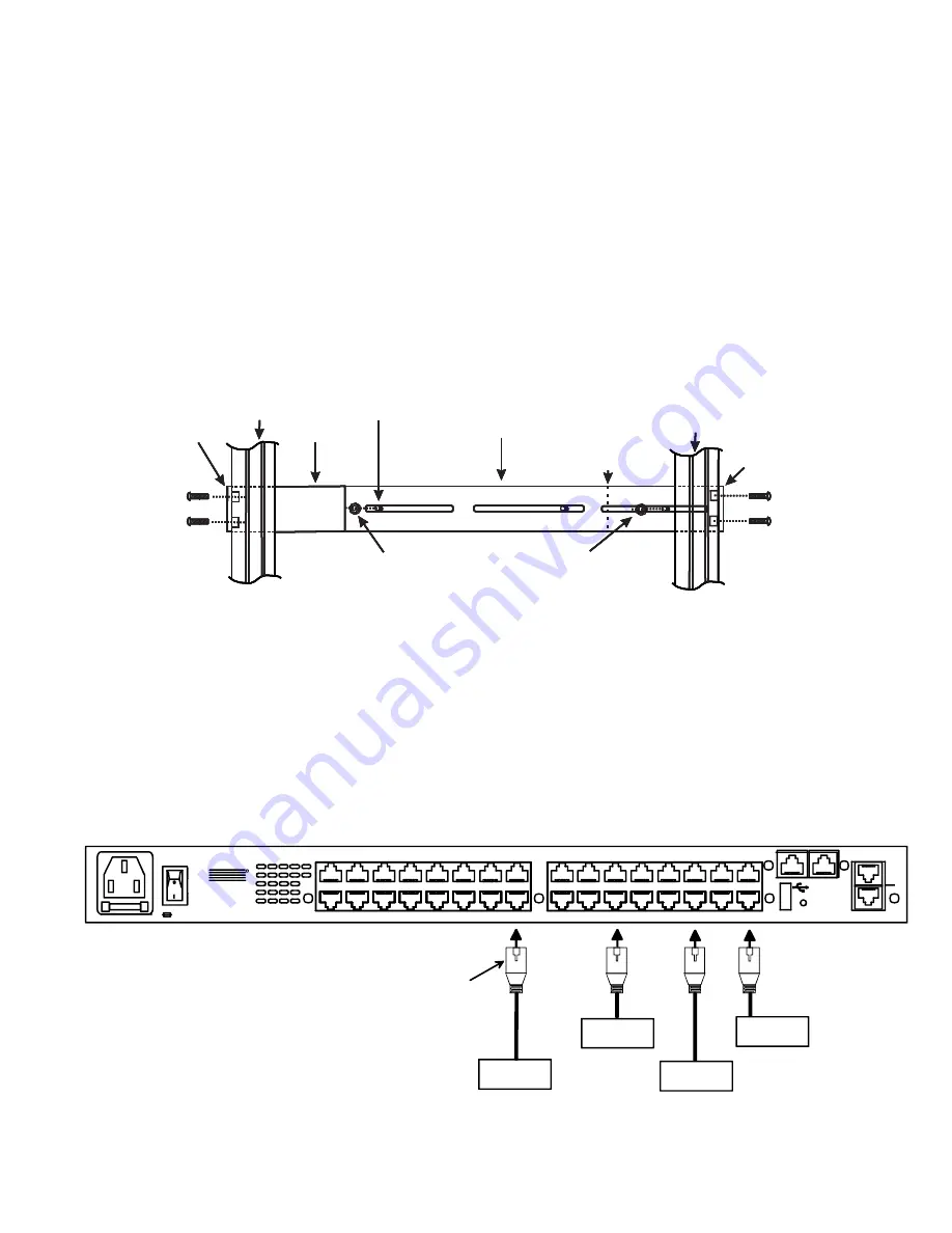
Hardware installation consists of the following steps:
1. Determine the mounting height in the rack for the drawer. It should be a height comfortable to use the keyboard and see the
LCD display. Mark holes in each of the 4 corner cabinet rails at points all level with each other.
2. Secure the rear brackets to the rear rack cabinet rails at the holes marked in step 1 using #10-32x3/4” screws and cage nuts
(supplied). Be sure to tighten the screws securely.
3. Lift the keyboard into position and line the studs on the left and right sides up with the slotted openings in the rear bracket.
Apply the nuts (supplied) to the studs but do not tighten the nuts yet.
FYI: There are 5 mounting studs provided on each side of the RACKMUX. Depending on the depth of the rack and
distance apart of the cabinet rails, the position of the rear bracket may make all 5 studs available for use. In this case,
apply the 2 nuts to the studs furthest apart from each other on each side.
4. Slide the drawer in until the top holes in the front bracket flanges line up with the holes marked in step 1. Secure the front
brackets on the drawer to the front cabinet rails using #10-32x3/4” screws and cage nuts (supplied). Be sure to tighten the
screws securely. Then tighten the nuts applied in step 3.
Note: Very deep racks may require the back of the rails to be bolted to an internal mid-rail within the rack, in which
case the rear rail extensions should be reversed so as to present the appropriate mounting holes to the rack mid-
rails.
Cable Connections
1. Connect each serial user device or host device to be connected by the SERIMUX to any serial port (1-4/8/16/24/32) using a
serial cable with an RJ45 male connector (image below). It may be necessary to add one of the cable adapters (supplied)
detailed in Appendix C of the manual between the device port on the user device or host device and the RJ45 connector.
2. Connect the power cord to the IEC connector.
3. Connect the Console Switch to the Ethernet for remote system management using the “ETHERNET1” or “ETHERNET 2” port
and CAT5/5e/6 patch cable.
Apply nuts (supplied) to studs and
secure rear brackets to drawer.
Front bracket
flange on drawer
Rear bracket
flange
Drawer
Front Cabinet
Rail
Rear Cabinet
Rail
Rear bracket overlapping
drawer
(Rear edge
of drawer)
Stud on drawer
Apply nuts (supplied) to studs and
secure rear brackets to drawer.
Front bracket
flange on drawer
Rear bracket
flange
Drawer
Front Cabinet
Rail
Rear Cabinet
Rail
Rear bracket overlapping
drawer
(Rear edge
of drawer)
Stud on drawer
Apply nuts (supplied) to studs and
secure rear brackets to drawer.
Front bracket
flange on drawer
Rear bracket
flange
Drawer
Front Cabinet
Rail
Rear Cabinet
Rail
Rear bracket overlapping
drawer
(Rear edge
of drawer)
Stud on drawer
Apply nuts (supplied) to studs and
secure rear brackets to drawer.
Front bracket
flange on drawer
Rear bracket
flange
Drawer
Front Cabinet
Rail
Secure bracket
to rail using two
screws and nuts
(supplied)
Rear Cabinet
Rail
Rear bracket overlapping
drawer
(Rear edge
of drawer)
Stud on drawer
Secure bracket
to rail using two
screws and nuts
(supplied)
SERVER
ROUTER
FIREWALL
RJ45
Male
Connector
Ethernet cable
PBX
1
2
3
4
RESET
5
6
7
8
17
18
19
20
21
22
23
24
ETHERNET
RJ45 SENSORS
AC INPUT
100-240VAC
20W
9
10
11
12
13
14
15
16
25
26
27
28
29
30
31
32
2
1
2A,250V
NTI
Tel:330-562-7070
Fax:330-562-1999
1275 Danner Dr
Aurora, OH 44202
www.networktechinc.com
R
Rear View of SERIMUX-T15-N-S32


