TxBlock-USB
NOVUS AUTOMATION
3/5
SOFTWARE AND APPLICATION CONFIGURATION:
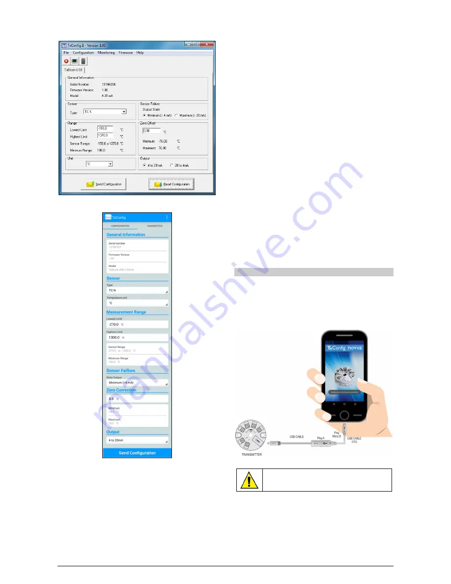
Fig. 10 – TxConfig II software main screen
Fig. 11 – TxConfig application main screen
The fields in the screen mean:
1.
General Information: This field shows information that identifying
the transmitter. This information should be sent to the
manufacturer in an eventual request for technical assistance.
2.
Sensor: Select the type of sensor to be used. See Table 1.
3.
Measuring Range: Sets de measurement range of the
transmitter.
Lower Range Limit: equivalent temperature for a current of 4 mA.
Upper Range Limit: equivalent temperature for a current of 20 mA.
Sensor Range
The values chosen cannot exceed the range of sensor shown in
this field. See Table 1 of this manual.
Minimum Range
Do not set a lower band (span) that the Minimum Range
indicated below in this same field. See Table 1 of this manual.
4.
Sensor Failure: It establishes the output behavior, when the
transmitter indicates a failure:
Minimum: Output current goes to < 3.6 mA (down-scale),
typically used for refrigeration.
Maximum: Output current goes to > 22.0 mA (up-scale), typically
used for heating.
5.
Zero Correction: It corrects small deviations presented in the
transmitter output, for example, when the sensor is replaced.
6.
Send Configuration: It applies the new setup. Once sent, the
setup will be immediately adopted by the transmitter.
7.
Read Configuration: Reads the current setup in the transmitter
connected. The screen now presents the current setup that may
be changed by the user.
FACTORY SETTING:
•
Sensor: Pt100 3-wire, range 0 to 100 °C
•
Sensor failure: upscale (maximum).
•
0 °C zero correction.
•
Unit: °C;
•
Output: 4-20 mA.
Upon purchase order, the user can define a specific setup.
SMARTPHONE CONNECTIONS
With the help of a specific cable, which allows smartphones to
recognize and configure TxBlock-USB when running the TxConfig
application, Android smartphones with On the Go (OTG) technology
can be directly connected to the device via the Micro-USB.
To do this, it is necessary to observe the connection mode of the
cable On the Go in the device, as can be seen in Fig. 12:
Fig. 12 – On the Go connection cable
Incorrectly positioning the cable end may cause
the device to be unrecognized by the application.


