


N1500FT Flow Indicator
NOVUS AUTOMATION
2/8
•
Open Sensor –
I.error
The open sensor alarm operates whenever the input sensor is badly
connected or broken. Valid only for 4-20 mA inputs.
•
Minimum Value –
Lo
It sets off when the reading is below the value determined by the
alarm Setpoint.
•
Maximum Value –
Ki
It sets off when the reading is above the value determined by the
alarm Setpoint.
•
Feeder Function –
FEEDER
It activates the output relay when it is started by pressing
or
via the auxiliary digital input (according to setup) and deactivates
when the reading reaches the value determined by the alarm
Setpoint.
ALARM TIMER
The indicator allows setting up an Alarm Timer, where users can set
the alarm to go off with a delay, to go off in only one pulse or to go off
in sequential pulses.
Figures in Table 1 show these functions. There, times T1 and T2
may vary from 0 to 32000 seconds and are defined while
programming the indicator. For regular operation of alarms, without
timers, simply set T1 and T2 to 0 (zero).
he alarm light signals will be displayed whenever there is alarm
condition, regardless of the current status of the output relay, which
may be temporarily out of power because of the timer function.
ADVANCED
FUNCTION
T1
T2
ACTION
Regular
Operation
0
0
Delay
0
1 to 32000
Pulse
1 to 32000
0
Oscillator 1 to 32000 1 to 32000
Table 1 - Alarm timer functions
ALARM HYSTERESIS
Hysteresis defines the difference between the value measured when
the alarm is triggered and the value at which it is deactivated.
INITIAL ALARM BLOCK
The initial block option prevents the alarm from going off in case there
is alarm condition at the time the indicator is being energized. The
alarm may be triggered only after a non-alarm condition is followed by
an alarm condition. This function is not valid for alarms programmed as
Open Sensor.
SPECIAL FUNCTIONS
MAXIMUM AND MINIMUM
The flow indicator continuously records the minimum and maximum
values of instantaneous flow rate. These values can be viewed on
the first screen of the main cycle by pushing
and
,
respectively. The
key can be set to zero maximum and
minimum values.
FEEDER
The feeder function is used to control the volume of fluids based on
its flow rate. It is typically used for storage applications, where there
is a start signal that triggers a relay and the flow rate begins to be
measured. When reaching a given setpoint, this relay is deactivated
to stop flow.
Its use depends on correct configuration of related alarm.
AUXILIARY DIGITAL INPUT AND
KEY
Similarly to a digital input, the
key can be set to zero the
totalizer, freeze the main screen, zero minimum and maximum
readings or trigger the feeder function.
MANUAL OPERATION MODE
In the hardware cycle, outputs can be set manually. This can be
extremely useful for tests and simulations. After exiting the cycle,
outputs go back to their regular status.
24 VDC AUXILIARY POWER SUPPLY
DC power supply models provide a 24 Vdc output for field transmitters.
INSTALLATION
The indicator must be installed on a panel. To do so, remove the two
plastic clamps, introduce the device in the panel cutout and put the
clamps back from the rear side of the indicator.
INSTALLATION RECOMMENDATIONS
•
Input signal conducers should be disposed in the system
separately from output conducers and power conducers,
preferably in grounded electrodes.
•
Instruments should be powered through a dedicated network.
•
For control and monitoring applications it is vital to consider what
might happen if any part of the system fails. The alarm internal
relay does not ensure total protection.
•
It is recommended to use RC FILTERS (47
Ω
and 100 nF, series)
in contactor coils, solenoid coils, etc.
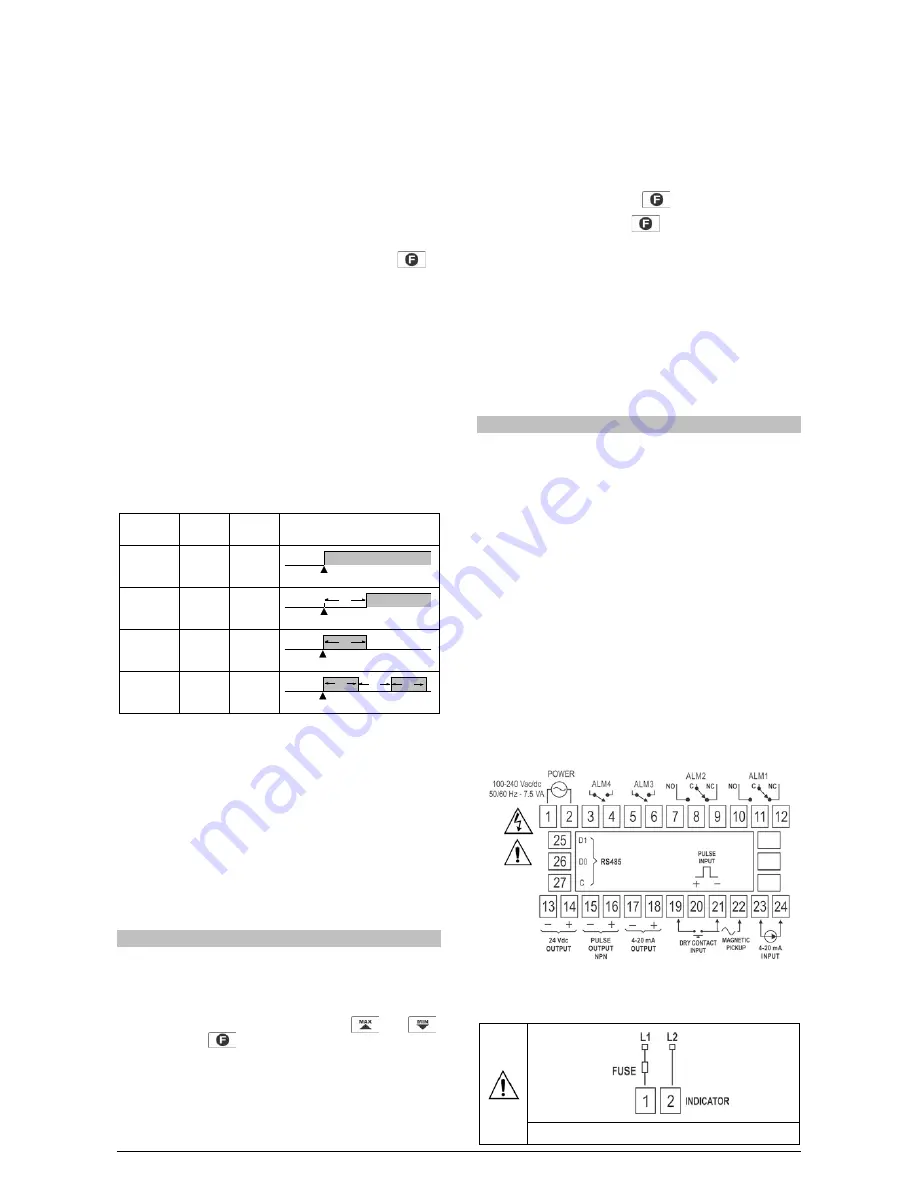
ELECTRICAL CONNECTIONS
All the inside can be removed without the need to undo the electrical
connections. Disposition of signals in the rear panel of the indicator is
shown in Fig. 1.
Fig. 1 – Rear panel connections
POWER SUPPLY CONNECTION
Fig. 2 – Power supply terninals
Alarm Event
Alarm
Output
Alarm Event
Alarm
Output
T2
Alarm Event
Alarm
Output
T1
Alarm Event
Alarm
Output
T1
T2
T1