


Operating Manual
LA-BO
Startup
MOUNTING & SETTING ON ALX 92X
Mounting
This chapter describes how to mount the LA-BO to an ALX 92x machine. The pictures show an ALX
92x (RH). For article numbers refer to chapter
on page 9.
Before you begin
Fig. 3: LA-BO for ALX 92x (delivery status).
Tools:
• Allen key 3 mm
• Small size screwdriver
At ALX 92x supplied before May 2007, 3 mounting holes have to be drilled in the ALX 92x ground-
plate. Please refer to service manual chapter “Repair & Maintenance” > “Pre-Installation of the LA-
BO on the ALX 92x” for detailed instructions.
Procedure
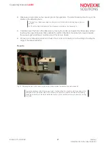
1.
Pull out the black top-left knob (A) and turn the LA-BO housing in the upper position (B).
Edition 05 - 08/2022
14
Startup
Mounting & setting on ALX 92x


