WAAS GUS Signal Generator User Guide Rev 1
19
Chapter 3
Setup Considerations
The Signal Generator is a device that is intended for use in dry stable environments.
For proper ventilation, the Signal Generator requires clearance of 6 inches minimum on all sides, except for the rear
panel, which should remain clear from obstructions. Installations not meeting this requirement must ensure a
minimum forced air flow rate of 1 cu-m/minute through the ventilation holes of the unit.
3.1
Front Panel Functionality
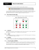
As seen in
, there is a power LED that glows green when power is applied to the Signal Generator.
Figure 7: Signal Generator Front Panel
3.1.1
H/W Fault
This LED glows red when there is an internal hardware fault. It will cycle on and off at a 1 Hz rate when the 1PPS
input signal is lost. See also
Section 5.1.4.6, Hardware Status Fields on Page 41.
3.1.2
10 MHz
This LED glows green when there is a 10 MHz reference present. The 10 MHz reference input level is in the range
+12 to +14 dBm and has an impedance of 50 ohms.
3.1.3
CW Mode
When the L1 CW Only or L5 CW Only switch is manually selected, the Signal Generator removes all modulation
from the L1 or L5 signal carrier respectively. The corresponding LED on the front panel glows red at the same time.
3.1.4
Transmit Inhibit (Tx INHIBIT)
This L1 or L5 Tx INHIBIT LED glows red if the L1 or L5 IF output is disabled. Incomplete L1 or L5 message data
transfer forces the unit to inhibit L1 or L5 signal transmission respectively for one second following the error.
This transmit inhibit function is controlled by a discrete signal that is applied via the Comparator input port. This
function is fail safe, so that if the control lines become open the transmission is inhibited.
Observe ventilation requirements.


