- 7 -
NOVATEK-ELECTRO
REV-201М
ATTENTION!!!
-
In this mode of operation time adjustment knobs (
T1
and
T2
) as well as the DIP switched for the time
ranges (
D1
and
D2
) doesn’t function. All timing frames and intervals are preprogrammed and fixed. On special
customer request for the algorithm “START-PAUSE-START” it’s possible to change the timing intervals and
delays as per requirement
-
REV-201M has internally preprogrammed block t
hat doesn’t allow to turn
ON
the power load on
Channel 2
until output contacts of
Channel 1
are being closed (
ON
).
1.3.3.5
“Impulse 2”.
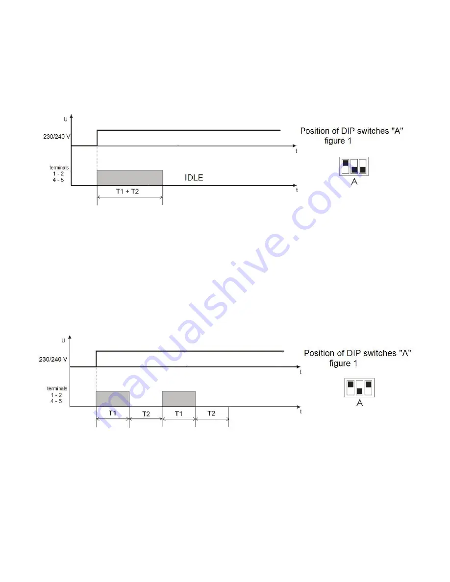
In the figure 6 there is represented the working algorithm of relay "Impulse 2
”.
Figure 6
– The working algorithm of relay "Impulse 2”
Time counting on each channel begins from the moment of power supply to the terminals «L1-N» (channel 1)
and «L2-N» (channel 2). The time delay is adjusted by the potentiometer knobs 3,5,10,12 (figure 1). Each channel
has two time setting adjustments
T1
and
T2
. The channel cutting off delay is defined by sum of delays arranged by
two potentiometers (
T1 + T2
).
At power supply on the channel there switches the load relay on, a red LED of this channel is on and the time
reading begins
T1 + T2
. After delay time period the load relay switches off, the LED changes the light to green and
the relay turns in standby mode.
The restart of relay is made after de-energizing and energizing again of power supply.
1.3.3.6
Intermittent 2
In the figure 7
is resulted the working algorithm of relay “
Intermittent 2
”
”.
Figure 7
– The working algorithm of relay “
Intermittent 2
”
Time reading on each channel begins from the moment of power supply to the terminals
«L1-N» (channel 1) and
«L2-N» (channel 2). Each channel has two setting adjustments T1 и T2.
At energizing the power supply to the channel the load relay switches on and the time reading T1 starts, adjusted
by the knobs of potentiometers 12, 3 (figure 1) for the 1-st and 2-nd channels correspondently
– time of work. The
red LED of the channel is on.
After the end of delay time period T1, the load relay switches off and the time reading T2 begins, arranged by
potentiometers knobs 5, 10 (figure 1) for the 1-st and the 2-nd channels correspondently
– time of pause. The LED
of the channel changes the light to green color.
After the end of delay time period T2, the load relay switches on, the LED changes color to the red one and the
cycle of relay work is restarted (the delay time reading
Т1 begins and so on).


